HYDROS 101
HYDROS 101

Whether you have been a fan for decades or are just learning about the sport of Unlimited Hydroplane racing, we want to help you learn about all facets of our sport – from a basic explanation of the races so you know what “heats” are and how to keep score, up to the intricacies of the Lycoming T-55 L7 gas turbine & Allison V-12 engines that power our boats and the aerodynamic forces that put the “plane” in “hydroplane”. It’s all here!
H1 UNLIMITED – THE SANCTIONING BODY
H1 Unlimited is the sanctioning body for the sport of Unlimited Hydroplane Racing in the Unites States. As a member of the APBA (American Powerboat Racing Association), we establish the rules that govern our races, the qualifications of the drivers, boats and the courses we run on. We also supply the personnel and equipment to put on the race at each venue, from the rescue crew to the media team to the tech personnel that insure everyone plays fair.
All of the members of the H1 Unlimited team are volunteers and all are long-term veterans of the sport, beginning as racers, crew, media or just plain fans. Most of our volunteers have been around boat racing for decades, involved at every level imaginable.
If you are at one of our races and want to learn more about the sport or volunteer your time, be sure to flag down a “Blue Shirt”!
The H1 Unlimited staff are volunteers that love the sport and it’s history and are working very hard to insure its future. From the Board of Directors to the Referees, Timing and Scoring, PA Announcers, Media and Technical staff, we all enjoy bringing the fastest boats on the water to your lakes, rivers and bays every year! Thanks for coming out to see races!
Meet the H1 Unlimited 2024 Staff:
H1 UNLIMITED BOARD OF DIRECTORS:
Mike Denslow – Chairman
Darrell Strong
Charlie Grooms
Shannon Raney
Kelly Stocklin
Brad Luce
REFEREES:
Jonathan Abbott – Head Referee
Matt Yarno – Assistant Referee
Sam Houghtaling – Assistant Referee
OPERATIONS:
Taryn Baze – Operations Director
Mark Mallory – Pit Boss
Jeff Shepherd – Assistant Pit Boss
Heidi Dunk-Vincent – Pit Operations
Don Agopsowicz – Truck Driver
Heidi Dunk-Vincent – Pit Operations
Suzy Shepherd – Risk Manager – Corral
Emily Raney – Credentials/Social Media
Ashley Raney – Credentials
RESCUE & MEDICAL:
Dave White – Director of Water Safety
Brannon Casler – Rescue
Dave Stering – Rescue
Joe Carrington – Rescue
Cathy Spry – Medical
TIMING & SCORING:
Jim Sharkey – Timer
Mary Compton – Timer
Nick Kish – Data
TECHNICAL:
Seph Parshall – Technical Referee
John Walters – Chief Inspector
Steve Compton – Tech Inspector
Brian Vincent – Tech Inspector
DRONES:
Lisa Courneya – Flight Director
Brian Montgomery – Drone Pilot
Dan Foard – Drone Pilot
MEDIA:
Tait Meyer – Live Stream
Jared Meyer – Live Stream
Matt Johnson – Live Stream
Chris Denslow – Photographer
Brad Luce – PA
Tana Morrisett – Media Liaison
Walt Ottenad – Website / Onboard Video / App
H1 Unlimited live-streams every session with boats on the water all season long on YouTube and Facebook.
Tait and Jared Meyer, brothers from Richland, WA established our current live streaming video program during the 2018 season and have refined it ever since. Beginning in 2024, our “Stat Man” – Nick Kish – took over the Livestream and included his wife, Rachel, cameramen Gio Belsito and Micky Washburn, and production assistant Tana Morisett to bring a full HD stream to any device that can receive it, anywhere in the world. We feel the livestream is the equal of any out there and brings you right to the shore for every one of our events!
At each race site, the crew sets up all of our gear the day before racing begins and tests the equipment, the connectivity and the final output so we are ready to bring our races to the world once testing starts. Every streaming session includes multiple camera angles from our on-shore cameras, drone cameras and remote cameras.
All sessions can be viewed on our YouTube channel and our Facebook page, as well as the H1 website – just click the “Video” menu item to watch all of our videos! Our livestream from San Diego is a great example of what you can expect from our streaming team:
In order to officiate our races, referees need to have an unobstructed view of the race course and all the boats on it.
In the past, this was accomplished by having a helicopter parked over each turn, with assistant referees in each one, keeping an eye on lane violations, overlap and other potential driving infractions. While helicopters were great for actually putting our referees eyes on the course, they were loud and rough, which made communication by the referees hard to hear and because having video evidence to review is critical to making the correct calls, helicopters were not ideal because the video our referees shot was EXTREMELY jerky due to the main rotor’s vibrations, as you can see in the following clip:
First discussed in 2014, H1 Unlimited began a feasibility study to determine if the helicopters could be replaced by drones, while still allowing referees to have the full picture of the racecourse as they would have from the helicopter.
Beginning in 2017, we started experimenting with drones that recorded video our referees could review after the heats were finished. The results were pretty extraordinary, but we could not rely on the video files to make decisions immediately, as the technology was not quite there to allow the real-time viewing that was required in order to shift completely away from the choppers.
In 2019, H1 Unlimited official Lisa Courneya established our Drone program that completely eliminated the use of helicopters by allowing our officials to see the view from each drone in real-time on monitors on the Judges Stand. Our drone team now includes Brian Montgomery, son of long-time H1 Unlimited announcer Steve Montgomery and long-time H1 contributor Dan Foard – the first person to fly an FAA-authorized drone over one of our events, in 2015. They bring a full complement of five DJI Mavic Pro 3 drones, along with hundreds of pounds of gear to each event to “fly” our referees to the prime viewing spots above each course.
The views from our drones are spectacular and allow a “camera on a pole” view from each turn on the racecourse, with an ultra-stable platform to view and record every heat. The video feed is sent from our pilot’s controllers directly to our video switcher, then to our Live Stream and the referee’s 35″ HDTV monitors equipped with DVR’s that allow them to immediately review their footage in order to make calls – most of the time before the boats even reach the dock!
Watch some of the drone footage in this Guntersville Final Heat review to get a feel for how much better the view is!
Society lives by rules and things are no different with H1 Unlimited. From what is allowed (and not allowed) on the boats to how the races are run and how the courses are set up, it’s all here.
THE RACES
Unlimited hydroplane racing has a long and colorful history, and the Hydroplane and Raceboat Museum is a great place to start learning more about the history of Unlimited hydroplane racing. The museum (also known as HARM) is located in Kent, WA and has an amazing collection of hydroplane memorabilia as well as many restored hydroplanes. Volunteers at the museum have restored some of Unlimited racing’s most beloved hulls: the 1955 Miss Thriftway , the 1957 Miss Wahoo, the 1962-65 Miss Bardahl, the 1973 Pay N’ Pak, the 1977 Atlas Van Lines “Blue Blaster” and the 1980 Miss Budweiser, among others.
At H1 Unlimited events in Tri-Cities, Seattle and others, exhibitions by some of the most famous hulls in Unlimited history are a part of the show. Learn more about the Museum’s mission by watching some of the videos below, and we wholeheartedly encourage you to visit the museum in person, and visit the websites we have included in the “Links” section below to learn more about the people, technology and the beautiful fast boats that make up the incredibly long and rich history of Unlimited hydroplane racing:
Boat racing in the Unites States has been going on since men first set sail, but organized powerboat racing began in the earliest parts of the 20th century and continues in a myriad of classes to the present day. The American Powerboat Association (APBA) is the sanctioning body for almost all forms of boat racing, but H1 Unlimited is the sanctioning body for all of our events except one.
Every year, Unlimited hydroplanes race for the oldest motorsports trophy in the United States: the APBA Gold Cup. The legacy of this trophy began in 1904, a full five years before what most consider to be the oldest motorsports trophy in the US: the Borg-Warner trophy given to the victor at the Indy 500. Except for a stretch during World War 2, the APBA Gold Cup has been awarded every year since 1904, and is the most prized trophy in Unlimited racing.
Unlimited hydroplanes have gone through five distinct periods of boat design and powerplant combinations: from the early part of the 20th century through the late 1940’s, conventional front engine, rear drive, deep “V” planing hulls that used a multitude of internal combustion engines were the standard and were not a huge break from then-current boat design norms. These designs stayed fairly static, with only incremental improvements.
In fact, the word “hydroplane” was not even associated with our class of boats until some pretty radical design changes were incorporated. In the early 1950’s, the second generation came in with a bang: the modern design standard of the round (or “shovel”) nose three-point hydroplane (a prop-riding boat with outboard sponsons that skipped on the water) began with what are widely regarded as the ancestors of modern racing hydroplanes: the Slo-Mo IV and Slo-Mo V, designed by Ted Jones of Seattle.
Almost all boats of the era were powered by then-plentiful WWII surplus aircraft engines and many colorful drivers were household names: Big-band leader Guy Lombardo, Chuck Thompson, “Wild” Bill Cantrell, Mira Slovak, Jack Regas and Bill Muncey among many others.
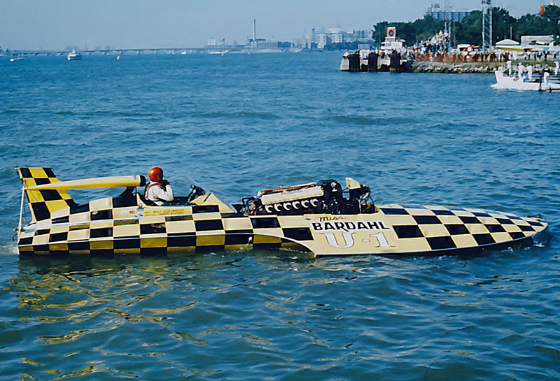
The U-1 Miss Bardahl – “The Checkerboard Comet” – was an example of state of the art hydroplane design in the late 1960’s. With Billy Schumacher driving, it won the championship in 1968. HARM photo:
In the design that dominated racing for almost twenty years, the driver sat behind the engine and the front of the boat had a rounded nose with the “sponsons” outboard of the center section, extending from the nose and ending about the back of the engine. The propeller on these boats was driven directly from the engine, so the engines were tilted at the same angle as the propeller shaft.
Unfortunately, these designs had disastrous consequences when the boats crashed, and many drivers were killed when the boats hit large swells, causing them to nose into the water at very high speeds. The worst day in the history of Unlimited racing occurred in 1966 at the Presidents Cup in Washington D.C. when three drivers: Don Wilson, Rex Manchester and Ron Musson were killed on the same day:
To try and combat these handling issues, some designers started experimenting with “cabover” designs, placing the driver ahead of the engine, changing the center of gravity to try and prevent these nose-first crashes. Even with more and more powerful engines, now capable of producing over 2,000 horsepower; the racing became marginally safer, but was still a very dangerous sport and drivers were still losing their lives.
Guaranteeing driver safety was a very slow process that had no clear-cut answer as the sport headed into the 1970’s. During the early 70’s, almost all consistent winners were still using aircraft power and the “conventional” round-nose hull.
The third generation of Unlimited hydroplane design came about with the popularity of the “pickle-fork”, or twin boom design familiar today that put the tips of the sponsons out in front of the center section.
Whether it was a conventional design or cabover, by the mid-70’s almost all winning Unlimiteds used this new design. Also, as surplus aircraft engines began getting more expensive in the early to mid1970’s, some teams began experimenting with now surplus turbine power plants that powered the Army’s helicopters.
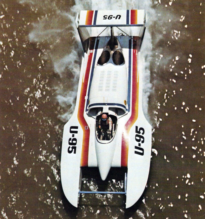
The fourth generation of Unlimiteds began in 1973 when a group in Seattle launched the U-95, a twin turbine design that ultimately started a revolution that changed the sport. It utilized two turbine engines and was the modern cabover “pickle-fork” design.
As costs continued to climb for the V-12 engines, the turbines were now becoming more readily available and were reliably churning out more horsepower than the internal combustion engines and requiring far less maintenance over the course of a race season. The integration of turbines was a very slow process, taking many years to prove that they were a match for the aircraft engines, but as the sport moved into the next decade, the winning combination proved to be the turbine engined cabover design, and Unlimited racing in the 1980’s proved once and for all that the turbines were the way forward.
The U-95 was the predecessor to the turbine Unlimiteds you see today. HARM photo:
As the aerodynamic portion of race boat design was becoming better understood, Unlimiteds also began taking advantage of these aerodynamic principles: the overall shape of the boats allowed them to function almost like a wing, with the “tunnel” under the boat being fine-tuned to allow the boat to more effectively use the air itself to lift the boat. Sponson designs of the “pickle-fork” boats were increasingly helping the boats to skip on the water easier and turn better.
Various teams started experimenting with other aero devices like rear wings, trailing moveable flaps to control the air at the front of the boat, and finally the modern moveable canard wing you see on our modern hydroplanes.
Three dominant hydros of the 1970’s and 80’s: the 1973 Pay ‘n Pak, 1977 Atlas Van Lines “Blue Blaster” and the 1980 Miss Budweiser:
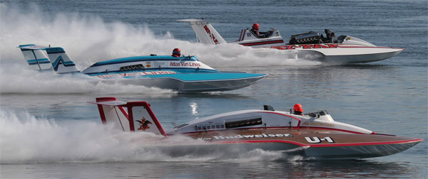
During every race, the driver and boat collect points for their qualifying performance and heat finishes. The boats that have accumulated the most points during the preliminary heats make it to the winner-take-all Final Heat. Note that we said “boats” – if multiple drivers drive the same boat and score points during an event, it’s the boat, not the driver that qualifies for the Final Heat. There is no guarantee that the boat that wins the Final Heat will come away with the most points.
Points are awarded for every session that features competition, such as qualifying, preliminary heats and the final heat. Points are not awarded for testing or exhibition runs.
For qualifying, the points break down like this:
- 1st Place qualifier receives 100 points
- 2nd Place: 80 points
- 3rd Place: 70 points
- 4th Place: 60 points
- 5th Place: 50 points
- 6th Place: 40 points
- Remaining boats that qualify above 130 MPH receive 30 points each.
- Boats that do not qualify or reach the 130 MPH threshold are awarded no points.
After each preliminary heat and the final heat, boats are awarded points based on how they finished. Each finishing place receives 75% of the points of the previous finisher :
- 1st Place: 400 points
- 2nd Place: 300 points
- 3rd Place: 225 points
- 4th Place: 169 points
- 5th Place: 127 points
- 6th Place: 95 points
- 7th Place: 71 points.
Points can be deducted for various rule infractions such as N2 or fuel violations, lane violations or unsportsmanlike conduct.
The winner of each race is determined by their finish in the Final Heat – points accumulated throughout the weekend have no bearing on their placing in the race – they only count toward the end of the season championship standings.
Points will count towards the National Champion Trophy for drivers and the National Champion “Martini & Rossi Trophy” for owners. Here again, there is no guarantee that the boat that wins the most races during the season will win the Championship.
For instance, the 2014 season saw J. Michael Kelly in the U-1 Graham Trucking win four of the six races, but Jimmy Shane in the U-6 Oberto took the Championship at the second to last heat of the season by virtue of accumulating more points.
Contrary to most other forms of motorsport that race on tracks with lanes or a starting grid where the cars will form up prior to the start and in their assigned starting positions, our drivers are free to try and grab any starting position they choose prior to the start, and that process starts with and is driven by a clock.
Each driver and crew chief will have their own clocks that they will synchronize EXACTLY to the official countdown clock so they can be as accurate as possible in timing their run up to the starting line, as the drivers will try to pass the start/finish line at EXACTLY 0:00 at full throttle – usually at around160MPH! Too soon, and they will have “jumped the gun” and will be issued a time or lap penalty, essentially ending their race. Considering that if the boat was traveling at 160MPH, it is covering 234 feet per second, so it shows just how critical that synchronization process is!
Prior to the start of each preliminary heat and winner-take all final, the official clock will count backwards starting at “10 to the 5” – this means that it is “ten minutes to the five minute gun”, or fifteen minutes to the start of the heat. This will be announced over the PA system but this callout is not super critical for the racers – this is when most boats will be lowered by crane into the water and drivers will be getting ready to enter the cockpit.
At “5 to the 5” (five minutes to the five minute gun), there will be another callout on the PA and usually in the driver’s earpieces from their radio man – and it is critical for them at this point to insure they are synchronized to the official clock. All drivers will be strapped into the boats with their safety gear in place and most will continue to check for exact synchronization with the official clock as each minute passes.
As the clock winds down to five minutes, there will be a ten-second count over the PA system. At five minutes, most drivers will fire their engines, leave the dock and enter the race course. The only exception to this is in Guntersville, where due to the length the boats must travel to enter the racecourse, they leave at six minutes.
At the one minute mark, or one minute “gun”, all boats must be up and running or they will be held at the dock and not allowed to take part in the race.
The 5 minute interval between the boats leaving the dock and arriving at the start is called the “milling period”, where each driver can go almost wherever they want on the race course to place themselves where they think they have the best shot at winning. What may look like a bunch of boats going slowly in circles is actually a VERY well thought-out process, and usually the subject of much planning prior to each heat.
Based on timing runs that each driver would have done in practice, he will know how long it takes him to pass the buoys on the course at a steady speed, so he will have a good idea of where he needs to be on the course and at what speed to allow him to make it to the start on time. However, these plans can definitely be thrown out the window based on lane position, positions of the other boats or other unforeseen circumstances that happen in the milling period.
You will likely see boats “cut the course” – moving from front stretch to back stretch and vice-versa through the infield at designated areas. This occurs when the driver is either out of place from where they need to be at a particular time, or it can be used to block another boat from grabbing an inside lane. However, there are areas inside the course where the rescue and judge boats are located, called the “DMZ” areas, and are clearly marked with buoys so the driver knows not to enter. If a driver does enter a DMZ, it is an immediate disqualification.
In the period before the start, all boats must maintain a minimum speed of 80 MPH as well, which is monitored via GPS on the onboard data logger and reviewed after each heat of racing. If it is discovered that the driver went below 80MPH for more than 5 seconds, they are disqualified. Look for the roostertail to be above the rear wing – if it drops below for any length of time, it’s a good indication the boat is going too slow and the driver may be in danger of that DSQ after his data is read.
Since the shortest way around the course is on the inside, Lane 1 is generally the preferred lane to start in, but the driver may definitely not want Lane 1 due to the way the boat is set up. If they have added taller gears in the gearbox or changed the propeller to maximize speed instead of acceleration, Lane 2 may be more to their advantage. Very rarely would any driver want to start from outside Lane 2. Since all boats were allowed to “fight for lanes” prior to the start, the driver that was the best at pre-race strategy usually ends up where they want to be and the rest of the field may have to run their race in a compromised lane choice.
Once lanes are established at the entrance to the turn prior to the start, all of the drivers will position themselves so that they reach the start/finish line as the official clock strikes 0:00, signifying the start of the race. Drivers do not want to “beat the clock” or they will be assessed a penalty, usually in the form of an additional lap or additional time added to their finishing time.
Keep an eye on any boats that are late to the start, ESPECIALLY if they have boats ahead of them on either side, as the run down to turn one can end up with the slower driver entering a “tunnel” formed by the roostertails of the faster boats, which is VERY powerful and can easily flip the boat or shred the canard, cowling and rear wing.
To sum up: if the driver and crew chief have done their pre-race planning, set up their boat correctly with the right gears and prop, synchronized their clocks, adhered to their timing marks, avoided other boats and grabbed their preferred lane, they MAY come away with a victory. If anything was overlooked or mistakes were made during the milling period, there are 4 or 5 other drivers that probably got it right and can take the win instead…
SAFETY SYSTEMS
By Dixon Smith
Question 1: Can a raceboat be made that will not flip?
Answer: Probably.
Question 2: Can that unflippable boat be a consistent winner?
Answer: Yes, but as one pundit said many years ago about another program, “when the Boeing Board of Directors changes the basic laws of Physics or gives us an endless budget, we can make this work.”
Real Answer: NO, not with current technology.
First a little history. Current race boats as we know them are generally called 3 point hydroplanes or prop-riders. This is because they ride on a small area at the back of each sponson and on the lower half of the propeller. The most famous first 3 pointer is the Slo Mo Shun IV. The Slo Mo IV was not the first 3 pointer, although it is the best known. There were a number of limited hydroplanes that were prop-riders prior to the Slo-Mo IV being built.
The first famous flip of a race boat occurred on Lake Washington in 1955 with the sister ship of the Slo-Mo IV, the Slo-Mo V, with Lou Fageol driving. The boat did a complete 360-degree flip and landed right side up, but with substantial damage. That happened over 50 years ago, and race boats are still flipping.
There have been several rather spectacular and famous flips in the unlimited class. In Pasco many years ago, the Pay ‘n Pak did a 720-degree flip, where it went around 2 times before hitting the water.
In San Diego in 1988, 2 boats, Circus Circus and the Miss Madison, did a side by side flip. A few years ago the Pico American Dream flipped in Seattle during a preliminary race heat, brought back to the pits upside down, repaired by the crew and ultimately won the final heat and the race.
There have been occasions where a unlimited race boat has done a 360-degree flip, landed right side up and continued running. When Steve David flipped the U-1 Oh Boy! Oberto in 2009 in Doha, the crew repaired the boat in time for the Final Heat, allowing Steve to take the 2009 High Points Championship!
Flips can injure the driver, but since the advent of the survival cell, very few drivers have been seriously injured and there have been no fatalities since the early 2000’s, when George Stratton was fatally inured in San Diego – mainly due to the lack of the HANS device (now mandatory for every driver).
Nearly all flips are disastrous to the boat – the least a hull can usually get away with is severe damage to the rear of the boat, and most boats that flip are very heavily damaged, requiring many hundreds of man-hours worth of repair before they can race again.
Corey Peabody flipped the U-9 Lynx Healthcare in Madison in 2022, just a week after winning the Gold Cup – doing extensive damage to the boat and taking it out of any further running in the 2022 season. The flip was so violent it ripped the entire right sponson off the boat!
Now, back to the questions.
First we need to understand a little about the physics of the problem. I will stay away from any equations, math or aerodynamic engineering stuff. I need to define a few things that will make this easier to understand.
Center of Gravity: The balance point of the boat. If you were to pick the boat up at only one point, and this was at the center of gravity, the boat would hang perfectly level. Without external forces, the boat will rotate around the center of gravity.
Center of Aerodynamic Lift: Some times called the center of pressure. If all of the aerodynamic lift were applied at the Center of Aerodynamic Lift, the effect on the boat would be the same as the real lift that the boat experiences.
Center of Hydrodynamic Lift: Same idea as the Center of Aerodynamic Lift, except the lift is from water, not air. These two are not in the same place.
Drag: All the stuff that keeps us from going fast. There is aerodynamic drag, drag from the air and hydrodynamic drag, drag from the water.
An interesting and important point is that water is about 800 times denser than air, or another way to say that is a bucket of water weighs about 800 times more than a bucket of air. If you don’t think air weighs anything or drag from air is not significant, hold your hand out the window of a car going 70 mph palm down, and then rotate your hand about 90 degrees and see what happens. Now think about that force, but multiplied 800 times, and you get an idea of the drag force from water.
Lift: To demonstrate aerodynamic lift, do the same experiment as above, hand out the window with palm down. Now rotate your hand a small amount in each direction and feel the upward or downward force. This is the lift force from the air. The same ratio of hydrodynamic drag to aerodynamic drag applies to lift. For a given speed and area, the lift from water is about 800 times the lift from air. That is why the sponson area in the water is very small compared to the total area of the boat.
Now, we need to have some stuff in the water, prop, rudder and skid fin. Anything else in the water is excess drag, and slows us down. So that is why to go fast, the boat needs to have as little sponson in the water as possible. The catch is how do we get as little sponson in the water as possible. Here is where those pesky laws of physics get in the way.
An arrow is a good example of something that works well aerodynamically. It has been developed over many thousands of years and has remained about the same for a long time, because it works. If you were to balance an arrow on your finger, you would find that the center of gravity is about 1/3 the distance back from the front. This is because the point on an arrow is somewhat heavy. The point being heavy is not only because it needs to be sharp and strong to penetrate a target or animal, but the weight up front makes the arrow more stable in flight.
Also, note the feathers are at the very back of the arrow. Remember the center of gravity is near the front, but the aerodynamic center is just in front of the feathers, very far back. Also, remember, per the definition of center of gravity, that the arrow, if disturbed in flight, will rotate about the center of gravity.
So if the arrow gets disturbed in flight and the front pitches up, it will rotate about the center of gravity, the tail will rotate down. When the tail rotates down, the feathers will increase lift and push the back up to re-level the arrow. If the nose of the arrow pitches down, the tail will rotate up, again around the center of gravity, and the feathers will push the tail down, again re-leveling the arrow. This is why an arrow flies straight and level. Arrows do not do 360-degree flips.
Well that sounds easy, let’s just design a boat like an arrow and make it stable. Here is where those pesky laws of physics and the practical world of boat racing don’t get along.
All raceboats have to be propelled by a water propeller. So, we need to keep the prop in the water. To do this, we need some significant weight on the prop. Most boats have about 1/3 of their weight on the prop and about 2/3 of their weight on the sponsons. To do this, means the center of gravity needs to be significantly behind the sponsons.
Remember that water drag is lots more than air drag, so we want to keep as much of the sponson out of the water as possible. The way this is done is to have the center of aerodynamic lift somewhat forward, to carry the sponsons, but not lift the prop out of the water. The result is the center of aerodynamic lift is forward of the center of gravity.
Two more pesky little problems rear their ugly heads about this time. The first is that lift goes up with speed, but much faster than speed. In fact, lift goes up with the square of speed. In other words, if speed increases 10% then lift increases 21%.
The other little problem is the center of lift is not in a fixed position, it moves around. The boat attitude, nose up or level, and height above the water both affect the position of the center of lift.
Here is the really bad news. As the boat pitches up, the overall lift on the boat increases. Remember the hand out the car window example and rotating your hand a small amount. Also, as the boat pitches up, the center of lift moves forward. Keep this in mind. Now, you say, but a lot of the boats now have canards that the driver can control.
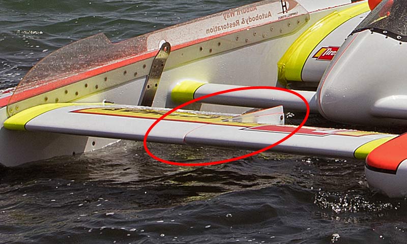
For those who don’t know about canards, it is a movable wing, forward of the cockpit that the driver controls, typically with his left foot. With the canard, the driver has significant control of the overall aerodynamic lift on the boat.
Let’s put this all together and put the driver in the loop during a race. Remember, less sponson in the water makes us go faster. Also, both aerodynamic and hydrodynamic lift go up with speed, but faster than speed.
One last thing, the aerodynamic center of pressure moves forward when the boat pitches up. Race water, a bit rough, accelerating down the straight, need to go faster so use the canard to lift the sponsons to get them just touching the water. Speed is increasing, all is good. Turn coming up, look for the other boats, and the sponsons hit a wave that the driver didn’t see.
Because hydrodynamic lift is so strong and increases faster than boat speed, the boat pitches nose up. Two critical things happen when the boat pitches nose up: (1) the total lift on the boat increases very fast with pitch up, and (2) the center of lift moves forward.
If the driver is a little late changing the canard position, or the pitch up is so much that the canard cannot overcome the increased lift and center of pressure moving forward, then up we go. Initially the boat rotates around the prop, but as soon as the prop is out of the water, now the boat rotates around the center of gravity. This is why it looks like the boat hangs with the nose up for a short period of time, then quickly does some type of loop or roll.
Other things that can set the boat off and start the process of a flip are wind gusts and the boat entering a turn. The aerodynamic lift is a function of air speed, which is boat speed plus or minus wind. So on a gusty wind day, a gust of wind could increase the lift unexpectedly. This is a typical situation in San Diego, because of the local topography. Depending on boat design, entering a turn can significantly change the aerodynamic characteristics of a boat. Not all, but a significant percentage of flips occur at the entrance to a turn.
Back to the question of can a boat be designed to not flip and also be a winner? With the right stability control system, similar to what some fighter aircraft use, yes. For some classes of raceboats, these types of control systems are illegal at this time. Also, it will be very expensive to develop this type of system for a raceboat, well beyond the budget capabilities of most teams.
In conclusion, a good boat design and an experienced driver are the best insurance against flipping a boat. But, so far, nobody has built a boat that will not flip.
© Dixon Smith Dixon Smith was a long-time crew member on the Miss Budweiser hydroplane team. He began his racing career in the ‘60s on the crew of the Hawaii Kai III and Seattle Too. He refurbished the 1962-65 Miss Bardhal and drives it at vintage hydroplane exhibitions in Kennewick, Seattle and Chelan, WA.
By Roger Schaffer
The following essay was written in the 1990’s, but most of the principles outlined here are the same for current Unlimited designs.
A blowover is probably the most spectacular accident in motor racing. They have haunted our sport since the Slo-mo V flipped qualifying for the 1955 Gold Cup in Seattle. I witnessed this accident and have been interested in their cause ever since. Even though serious injuries and fatalities have been prevented by the enclosed cockpit, the high incidence of these accidents is a real cause for concern. By my count there have been at least 32 blowovers since the Slo-mo V flip. This last year alone there were six flips. The incidence of accidents has increased even though the boats have become much more technically sophisticated and many designs have been wind tunnel tested. What is going on here and how can the frequency of these accidents be reduced? This article examines the underlying cause of blowovers and makes some suggestions on how they can be reduced. Please don’t be put off by the technical terms. After this article you’ll be able to snow just about any hydro fan.
Lets face it, a hydroplane is basically a very low flying airplane. It makes sense that the same principles that apply to airplane stability can be used to understand blowovers. First, when is a hydro an airplane? Clearly when the aerodynamic lift is more than the weight of the boat, its an airplane (the rudder, skid fin and prop might still be in the water, but for all intents and purposes the hydroplane has become an airplane). Airplanes always take off when going into the wind and hydroplanes almost always blowover when going into the wind. This is because aerodynamic lift is due to the square of the relative wind speed over the wing. If the boat is doing 180 mph and hits a 20 mph wind gust it suddenly sees a 200 mph relative wind and the aerodynamic lift increases by 24 percent ((200/180)**2=1.24). In fact the speed at which a hydroplane becomes an airplane can be pretty accurately estimated by the formula: V = 45 x (W/S)**.5
In this formula V is the relative wind speed in miles per hour when the hydro is completely airborne. The term W/S is the wing loading and is simply the total weight of the boat divided by its deck area. The wing loading for current hydros is around 17 to 22 pounds per square foot. The square root of these values is between 4.1 and 4.7. This puts the blowover velocity at 185 to 210 miles per hour less any wind gusts. This formula tells us what we already know: light boats with lots of wing area fly (and will blowover if not stable) at lower speeds then heavier boats.
To keep from blowing over when in the airplane mode the hydro must have positive stability. This means that if the bow pitches up, even a little, there must be a “moment” produced by the boat that tends to pitch the bow back down. (A “moment” is simply a force that acts through a distance. A more common term for moment is “torque” and either term can be used. A wrench produces a moment or torque by applying a force multiplied by the length of the wrench.) If the moment produced by the boat is not strong enough, then the bow will continue to rotate up and over. What causes the stabilizing and the restoring moments? That is the essence of stability, but first some terms must be defined.
For safety, every airplane has a forward and aft limit on its center of gravity location. This location is established by the manufacturer and is based on the design of the airplane and FAA regulations. The “center of gravity” is the point where all the weight can be considered to be concentrated; it is the point where an object would balance if hung from a single cable. If a hydro is horizontal when lifted off its trailer, its center of gravity will be exactly between the forward and aft lifting points. If the boat points bow up when lifted, its center of gravity is aft of this mid- point. The aft most location of the center of gravity where an airplane is stable is called the “neutral point”.
For our purposes, the neutral point is the same as what engineers call the “aerodynamic center”. The aerodynamic center is the point where the aerodynamic lift can be considered to be concentrated and where the aerodynamic moment is constant. Sometimes you will here the term “center of pressure” used. It should not be confused with the “aerodynamic center”. The center of pressure is where all the aerodynamic lift can be considered to be concentrated and where there is no net aerodynamic moment. The problem is: the center of pressure moves allover the place depending on the angle of attack and height of the hydroplane. The neutral point does not move with angle of attack. Unfortunately, for most hydroplane configurations, it also changes with height above the water. Nevertheless, the neutral point is a better concept to deal with.
It is relatively straight forward for an aerodynamicist to determine the location of the neutral point for an airplane. This can be done using mathematical equations or by wind tunnel testing. However, it is very difficult to establish the neutral point for a hydroplane because of the effect of flying very close to the water. This so called “ground effect” greatly changes the way the air flows around a shape. It makes it hard to estimate the neutral point either analytically or by wind tunnel tests. To understand why ground effect causes this difficulty it is necessary to understand how the air flows around a hydroplane.
Air that hits a hydro between the sponsons either goes over or under the boat. The air that goes over the top will create a suction pressure due to the curvature of the shape, just like the upper surface of an airplane wing. This low pressure tends to be concentrated at about 25 percent of the length of the wing aft of the leading edge, just like an airplane. The air that goes under the boat behaves much different than an airplane due to the presence of the water surface. The bottom of a hydroplane is basically flat and slopes down from bow to stern.
You can better visualize the bottom shape of the boat by looking at the trailer when the boat has been removed. This bottom angle plus the sponsons and “air traps” along the sides form a scoop. This scoop stops or “stagnates” the air and generates the same type of pressure you feel if you cup your hand and hold it outside a car window. This pressure is pretty much the same all over the sloping part of the bottom of the boat. Therefore, the lift force from the underside of the boat is concentrated close to 50 percent of the distance back from the leading edge of the wing to where the slope ends.
The stability problem is largely due to the fact that the upper and lower surface lift forces act at different locations. The stability problem normally begins when the aerodynamic lift on the boat exceeds the weight of the boat. As shown above, this can easily happen when a head wind or gust is encountered. When the aerodynamic lift is greater than the weight there is a net upward force on the boat and the boat tends to move away from the surface of the water. Even a small upward movement allows more air to escape from the transom and sides of the bottom surface. This increased area for the air to escape is like a leak that allows the air bubble of stagnant air that the boat has been riding to escape more easily. The air pressure under the boat decreases while the air pressure on the upper surface does not change.
So a boat that was in perfect balance just an instant before hitting the gust now has a net bow up moment acting on it. This new torque is due to the change in lift on the under side of the boat and the fact that the upper and lower surface lift forces act at different locations. This new torque tends to rotate the bow up. If there is no other lifting surface (like a horizontal stabilizer) to produce a torque to counter balance the bow up torque, the boat will continue to rotate producing the classic blowover.
This explanation leads to the conclusion that boats without horizontal stabilizers will tend to blowover when ever the aerodynamic lift exceeds their weight. (The rudder and skid fin produce a moment which tends to keep the bow down, but only to a point.) Adding a horizontal stabilizer helps, but will not prevent a blowover. The restoring torque that the horizontal stabilizer produces is due to its surface area, distance from the center of gravity of the boat, and rate of change of its lift with angle of attack. If the center of gravity is aft of the neutral point the restoring torque will be insufficient to counter balance the destabilizing torque produced by the change in lower surface pressure. Even with a horizontal stabilizer, there will always be a center of gravity location where the boat will be unstable. Changing the angle of attack of the horizontal stabilizer does not move the neutral point; it only changes the amount of lift that it produces which changes the attitude of the boat which indirectly changes the blowover speed.
Most boats now have small wings that connect the sponsons and the fuselage. These “canards” have flaps along their trailing edge that the driver can control. These canards can change the attitude of the boat and can improve the stability of the boat if operated precisely by the driver. However, this is very difficult and because they produce a lifting force forward of the center of gravity they actually move the neutral point forward, closer to the center of gravity, which is destabilizing.
Several boats including this years T Plus have tried the two-wing (tandem wing) design. The advantage of this configuration is that the neutral point does not move forward when the height of the boat above the water increases; the neutral point remains fixed like on a conventional airplane flying out of ground effect. This makes it easier to estimate the location of the neutral point. However, it does not mean that two-wing boats can not blowover – they still can if the center of gravity is aft of the neutral point and the boat exceeds the blowover speed.
There are other mechanisms that can cause blowovers. The most common are the sudden lost of the rudder, skid fin or propeller blade. For example, the Miss KISW flipped in a practice run in Seattle this summer when its rudder came off. The rudder and skid fin produce a large amount of drag. Because this drag is below the center of gravity they tend to hold the bow of the boat down. When the rudder or skid fin suddenly come off this restoring moment is lost and the boat is left with a net aerodynamic moment that tends to pitch the bow up. Again, unless the center of gravity is far enough forward and the horizontal stabilizer is big enough, the boat will continue to rotate up and over.
Until recently the loss of a propeller blade would often cause a blowover. The propeller produces a considerable amount of lift this is what holds the back end of the boat out of the water. Because this lift is well aft of the center of gravity the propeller lift tends to hold the bow down. The loss of a propeller blade, just like the loss of a skid fin or rudder, leaves the boat with a net bow up torque. If the boat is at or above its blowover speed it will flip unless there is sufficient restoring moment. Horizontal stabilizers and the “shoes” on the transom of most boats are helpful in producing this restoring moment and the loss of a propeller blade is much less of a problem then it once was.
Another situation that can cause a blowover is inadvertent movement of the center of gravity. If a boat gets a significant amount of water in its bilges and the water moves to the aft end of the boat, the center of gravity can move far enough to make the boat unstable. This was the cause of the flip of the 7 litre hydro Record 7 that almost killed Tommy Fults during a straight away record attempt in 1969. Boats should be designed to prevent the accumulation and movement of water inside the boat. Likewise, the fuel tanks should be at or aft of the center of gravity to prevent the center of gravity from moving aft when the fuel is burned off.
Is it possible to prevent blowovers? Probably not. However, it should be possible to reduce their frequency. The best solution would appear to be high quality wind tunnel testing to determine the location of the neutral point and its movement with height. Constant monitoring of the center of gravity to keep it forward of the neutral point by a safe margin would then be necessary. Wind tunnel testing is expensive and simulation of the ground effect is difficult. However, the cost of a blowover is also expensive, both in terms of damaged equipment and injuries to the driver.
Another option is to develop a design that automatically “bleeds off” excess air pressure to hold the aerodynamic lift to a value slightly less than the weight of the boat. If this could be done the hydroplane would never become an airplane.
Blowovers will likely remain a threat in hydroplane racing. However, they do not have to be a certainty, depending only on the next gust of wind. I hope this article helps in the understanding of these spectacular accidents.
In the previous section, you’ve seen what can happen when the boats flip, and that’s only one of the potential dangers to our boats and drivers.
A single blade inside a turbine engine can fail, leaving $100,000 worth of scrap metal in it’s wake. Gearboxes can fail, turning $50,000 worth of precision machined parts into a pile of junk. A tiny crack on a propeller can suddenly cause a blade to break at 9,000 RPM, ripping the back half of the boat apart, potentially sending it to the bottom.
Unlimited hydroplanes are some of the most spectacular racing vehicles on the planet and put on an amazing show any time they are on the water. Unfortunately, in any machine traveling 200+ MPH on the water, there are a LOT of things that can go wrong.
COLLISIONS:
At the 2017 Gold Cup in Detroit, Bert Henderson spun in front of J. Michael Kelly’s U-12 Graham Trucking hydro, leaving Kelly nowhere to go but over the top of Henderson’s U-7 Spirit of Detroit. Fortunately, neither driver was injured in the accident.
At the 2013 UIM World Championship in Doha, Qatar, Tom Thompson’s U-11 Peters & May ran wide into Brian Perkins’ U-21 Snoqualmie Casino and ended up being catapulted up and over the top, into Doha Bay sideways at 130+ MPH. The impact completely destroyed the U-11 and severely damaged the U-21.
In one of the most dramatic examples of things going wrong in recent memory, the video below shows the final heat at the 2011 Madison Regatta from onboard the U-1 Oh Boy! Oberto. In the final, Dave Villwock in the U-96 Spirit of Qatar was leading Steve David in the U-1 Oh Boy! Oberto into turn 1 on lap 4 when Villwock hit a “hole” in the water, snapping the boat sideways directly into the path of David, and at over 100 MPH, there was no time to react.
Due to the tremendous strength of the structure in both boats and the safety features built in, Steve David suffered only some cracked ribs and Dave Villwock was unhurt in the accident. The U-96 raced the following weekend in Detroit, the U-1 was on the water later in the season.
Cockpit design has evolved over dozens of years of racing and has progressed to the current design, which is a more or less standardized “survival cell” for the driver.
The cell is framed in tubular steel and wrapped in composite and carbon fiber to make it as strong as possible, with a similarly constructed lid on top and an escape hatch with a Lexan window in the floor. There is a steel spar that spans between the sponsons and attaches to the front of the cockpit, forming an incredibly rigid structure that can withstand almost any impact.
The windshield is from an F-16 fighter jet and side windows are usually made of bulletproof Lexan. 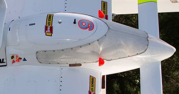
Almost all modern hydroplanes use the newest cockpit design that incorporates a roof hatch that opens forward, but some older boats still use a hatch that hinges open to the side. These are being phased out due to the additional safety margin of the newer designs.
In the video below, in Heat 2A of the UIM World Championship in Doha, Qatar, Brian Perkins’ U-21 Snoqualmie Casino was run over by the U-11 Miss Peters & May of Tom Thompson. This dramatic video shows how the survival cell kept Perkins safe, allowing the U-11 to roll over the top of the boat rather than entering the cockpit. Perkins was uninjured in the incident and Thompson suffered a relatively minor arm injury.
Normal access to the cockpit is through the top hatch, but if a hydroplane flips and lands upside-down, the driver needs a way to get out. Since the roof hatch is now under water, it cannot be opened, so the only practical way for the driver to get out of the cockpit is through the escape hatch built into the floor.
All hydroplanes have this mandatory escape hatch, and it can be opened either by the driver from inside the cockpit or by rescue personnel from outside if the driver is incapacitated. The hatch covers and latches are standardized so all drivers and rescue personnel don’t have to memorize any boat’s particular arrangement in an emergency, which can cost valuable time in a recovery.
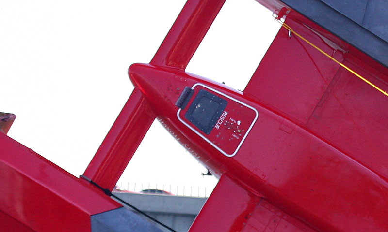
All current hydroplanes have escape hatches with a Lexan window that allows rescue personnel to see inside the cockpit prior to opening the hatch. Although flips are fairly infrequent, the hatches have been used a few times in the past decade and in every case, they performed as intended, allowing the driver to exit the (now underwater) cockpit quickly.
In the clip below, you see J. Michael Kelly flip the U-7 at the Columbia Cup in 2007, and very shortly after the boat has settled in the water, he opened the escape hatch and climbed out.
The driver wears a standard open-faced, rather than a closed-face helmet. This arrangement allows him to wear the air mask that provides an air supply and radio microphone, as well as attachment points for the required HANS device. Some drivers may also mount a visor or a fighter pilot style glare shield that flips down in front of their eyes instead of sunglasses to cut down on the considerable glare experienced at some race sites, particularly in the latter part of the day as the sun lowers on the horizon.
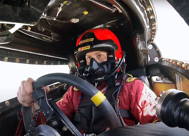
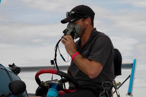
The air mask is the single most important piece of safety gear the driver has. In the event of a flip, the cockpit may fill with water and the air mask functions the same as a scuba diver’s regulator, providing air to the driver from an onboard scuba tank located behind the cockpit. This air supply is good for at least 15 minutes.
The mask also contains the microphone for the boat’s radio system, allowing the driver to communicate with his radio man. The microphone “talk” switch is normally a button located on the steering wheel and the radio speakers are contained in custom-fit earplugs that the driver may tape in place to keep them from being jarred loose. Both the air and radio systems have connectors that allow the mask to be connected and disconnected quickly.
Here Jimmy Shane tests the air mask for proper operation prior to testing – also note the earplugs:
Just like NASCAR, Indy Car and other top tier motorsports, our drivers wear a HANS device while driving their Unlimited hydroplanes.
HANS stands for Head And Neck Support and was developed to greatly reduce the possibility of head and neck injury to the driver by helping to immobilize the head during violent crashes. The HANS device operates by fitting a support made from carbon fiber shaped in a “U” across the driver’s shoulders with the portion behind the driver’s head raised in order to hold tethers that attach to the helmet.
Once the driver is strapped in, the HANS device is held under the seatbelts, forming a solid anchor for the tethers.
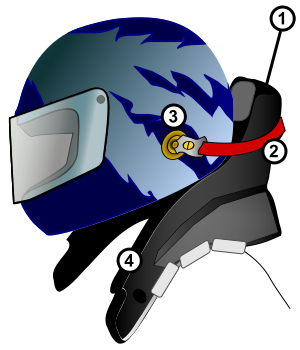
1. HANS device, 2. Tether (one per side), 3. Helmet anchor (one per side), and 4. Shoulder support.
During a crash, the tethers limit the range of motion of the driver’s head, helping to eliminate the possibility of head and neck injury. Almost all boats also include a padded structure (head rest) on the right side of the seat that limits the motion of the driver’s head during hard cornering. Considering that our boats corner with 5+ G forces, this helps the driver keep his head upright.
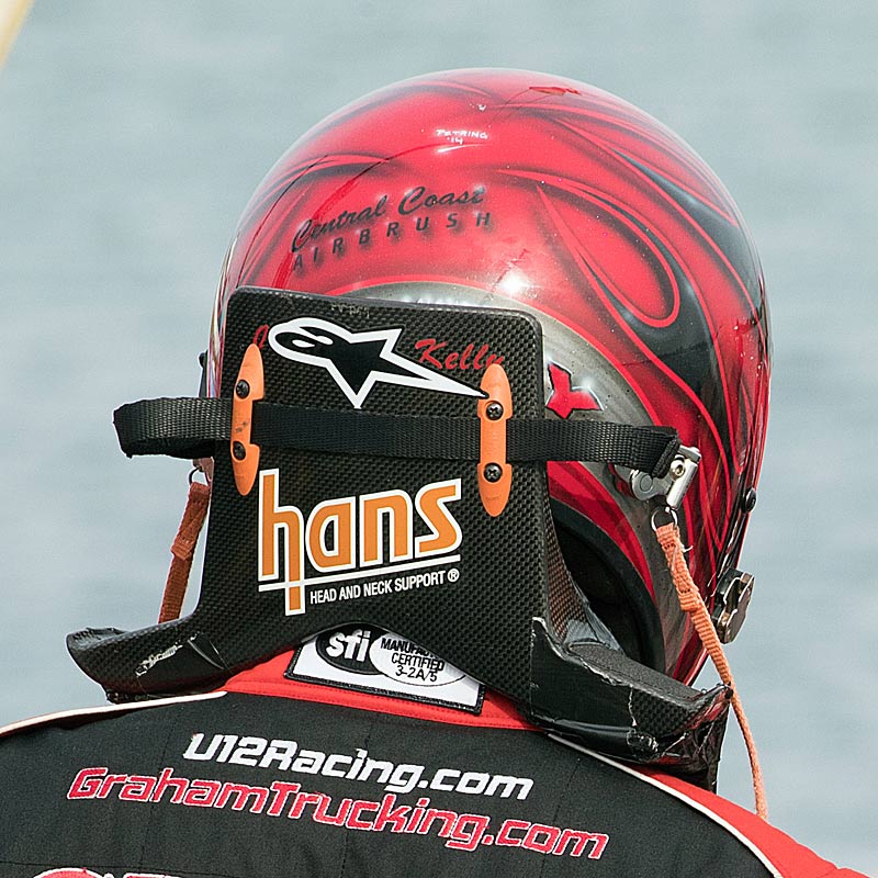
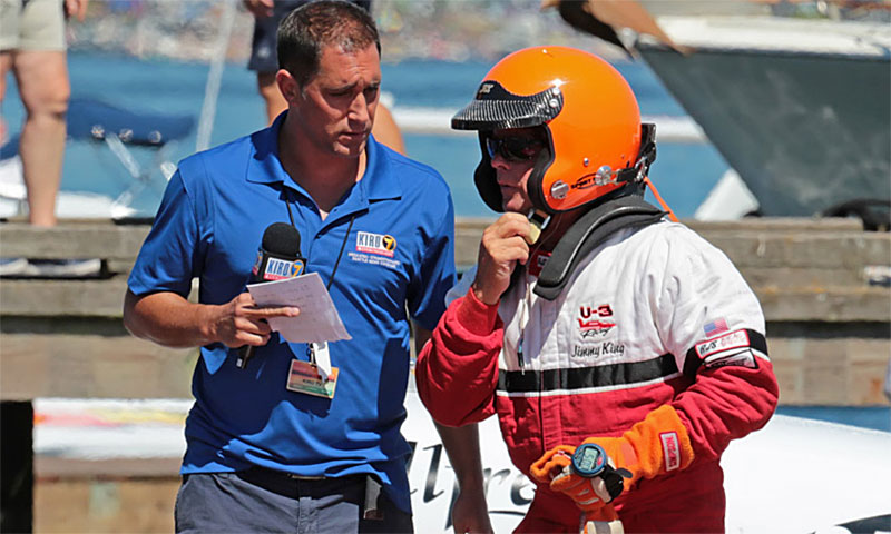
The driving suit worn by H1 Unlimited drivers is of the same type you would see in any top tier motorsport – H1 rules require that the driver’s suit be fire retardant with tight fitting cuffs. Gloves and racing shoes complete the suit. A flotation vest or life jacket is also required, and this may be either under or over the driving suit.
THE DRIVER
To drive a modern Unlimited Hydroplane competitively requires years of experience, usually gained in lower classes of inboard or outboard racing, with many drivers having started racing at the minimum APBA-sanctioned age of 9 years old. Experience alone does not guarantee a driver will end up in one of these boats, but it almost always will determine whether or not they will be successful.
In order to even qualify to drive an Unlimited hydroplane, a driver must be a certified SCUBA diver, pass a capsule training program, pass a physical examination, pass a test on the rules and then prove they are capable of producing the requisite speed – a driver must run a minimum of 15 timed laps (during one season) under the observation of the Chief Referee, 2/3 of which need to be above 130 MPH in order to start in a race.
Once the driver qualifies, they must start five seconds behind the front row for their first two heats of racing, and even then can still be assigned an outside starting position if the Chief Referee deems them needing more experience.
Only when the Chief Referee “signs off” on a driver are they fully qualified to compete from any starting position In contrast to Unlimited racing 40-50 years ago, drivers enjoy longer careers mainly due to the advancements in all aspects of the safety systems built into in our boats. Today’s drivers are also younger on average than in years past, with most of our current drivers under 40 years of age.
For almost all of our drivers, H1 Unlimited is a small part of their annual racing schedule, and when not racing Unlimited hydroplanes they can usually be found racing other classes of boats at local events around their hometowns and in national events.
The video below shows J. Michael Kelly in the cockpit of the U-5 Graham Trucking during the Final Heat at the 2015 Gold Cup, showing how brutal a ride in a modern Unlimited hydroplane can be, regularly subjecting the driver to lateral loads over 5 G’s and instantaneous vertical loads approaching 10 G’s.
The cockpit of a modern unlimited hydroplane is a very cramped space. There is not much room for anything that is not necessary to run the boat. In fact, just to allow the driver to get in and out of the cockpit, the steering wheel must be removed.
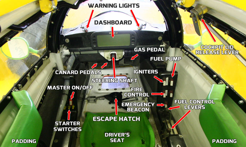
To enter the cockpit, the lid on the top of the cockpit is hinged at the front and flips up to allow the driver to enter. There is a release lever that allows the driver to open the lid from the inside and this is duplicated outside the cockpit as well.
Once the driver is situated in his form fitted seat, he gets strapped in with a five-point harness system that has a single release to quickly unbuckle all of the belts at once in case of an emergency. The driver cannot tighten these belts himself – this must be done by crew members who are helping him get ready. The rule of thumb is that when you get them tight enough that you can’t breathe, tighten them some more…
On either side of his head are padded supports for his head that limits the amount his head can move during 5+ G turns. In conjunction with the mandatory HANS device, the driver is using the latest in safety technology.
His feet rest on three pedals: the one on the right is the gas pedal, just as you would find in your own vehicle, but the two left pedals operate the front canard system, allowing the driver to control the attitude of the front of the boat with his left foot – push down on one pedal to lower the rear edge of the canard and raise the nose of the boat, or push down the other pedal to raise the rear of the canard, pushing the front of the boat down into the water.
Under the driver’s legs is the escape hatch that is his only way out if the hydroplane ends up upside down. All drivers must pass a capsule training test in order to race an unlimited hydroplane.
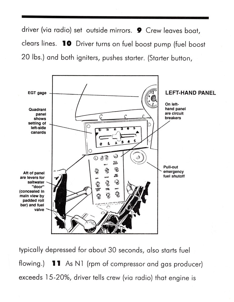
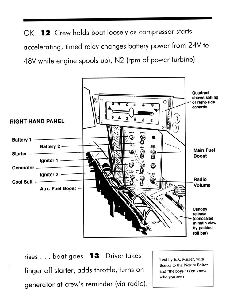
On the dashboard is usually a display panel or gauges that give the driver information on the engine such as N2 RPM, exhaust gas temperature (EGT) or other parameters. Usually there are one or two lights on the dashboard as well – these warn the driver when they are approaching the upper N2 RPM limit.
There are switches that control the flow of electricity to various items: a master on/off switch, emergency beacon, fuel pump, igniters, 24 and 48 V power for starting, and switches for the onboard Halon fire extinguisher system.
There are also levers that control the flow of fuel to the engine and since the engine will continue to run as long as it receives fuel, the adjustment on these levers is critical – this is the only way to turn off the engine once it has been started, so they have to be calibrated correctly.
The master switch for the electrical system and the fuel shutoff controls are duplicated on the outside of the cockpit as well so that rescue team members or crew can shut off all the systems on the hydroplane.
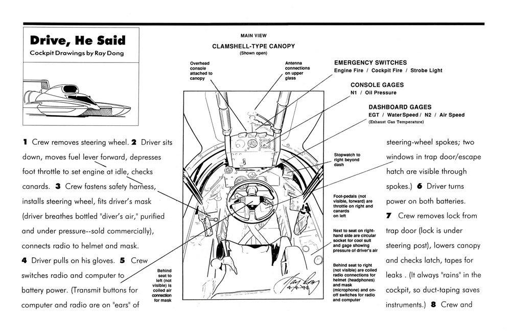
In the following infographic (courtesy of Ray Dong), you can follow the steps the driver and crew go through to get the driver ready and the boat started – there is a lot going on before the driver can even leave the dock!
THE TEAM
To get an Unlimited Hydroplane race-ready and competitive requires thousands of man-hours and tens of thousands of dollars to run each event. Without a well-oiled team to keep them afloat, these boats would be nothing more than fancy display pieces. A modern unlimited team requires workers to build (and rebuild) the boat, manufacture parts and modify boat systems, rebuild and install the engines and service the gear boxes, machine and care for the props, set up the wings and skidfins and program the computers and insure all the onboard electronics function. And that’s just what it takes to get the boat to run on the water!
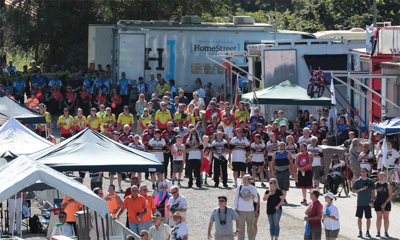
Every team also needs a truck driver to haul the boat to every event and someone in charge of getting the rest of the crew on airplanes and into hotels during every event.
Once the team is assembled at the race site, they go to work getting the boat ready to run, and depending on the amount of damage their boat incurred at the previous race this may be a 2-3 hour process or it may take all day and most of the night! It’s no small task to bring along everything that could possibly be used or consumed during the course of a race weekend, but our teams are professionals that have been at it a long time.
Every team tries to come with what they need to be self-sustaining, but circumstances may throw their plans out the window! If a team needs help with spare parts, or their boat suffers damage that can’t be fixed with their own crew members in time for the next heat, it’s not at all unusual to see members of every team in the pits come together to “get it done” and get the boat back on the water!
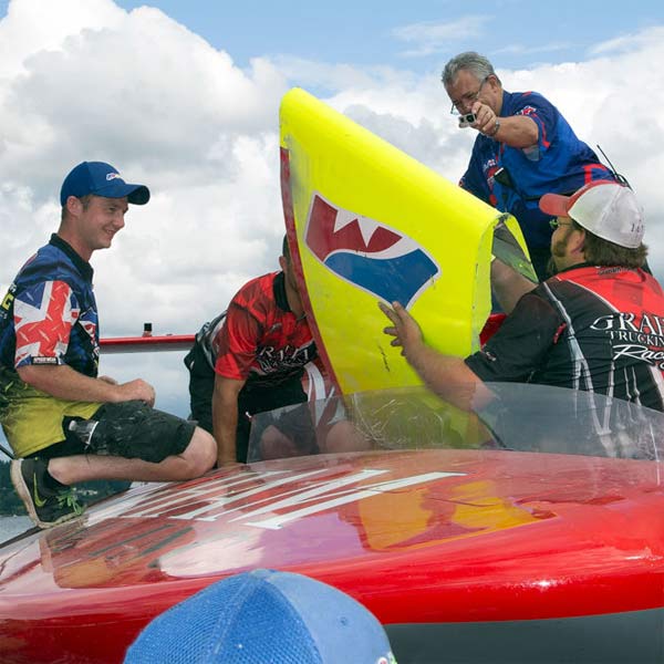
Above: The U-11 Unlimited Racing Group team lends a bullnose to the Graham Trucking team in order to get them back on the water for the final heat in Seattle
Every Unlimited team has crew members that have been involved in racing boats for dozens of years, and most of their experience has come from doing multiple jobs on the various crews they have been part of. In other words, there is no “school” for becoming an Unlimited crew member – this is truly a sport where “on the job training” is about the only way to prepare someone for their position on the crew.
In addition, almost all teams have new crew members on the staff, and they will be picking up knowledge from the other crew members during every day at the shop, test event or race. If you ask around the pits, most crew members became involved through friends, relatives or just by “hanging around the shop” until someone gave them a broom and told them to clean up!
Most teams also have experts in the various disciplines: hull fabrication and repair, engines, gearboxes, propellers, wing and canards, cockpit systems, electronics, data and setup. These experts can come from the inside – through experience on Unlimited crews, or from the outside – turbine engine technicians from aerospace or propeller technicians from commercial propeller manufacturers, automotive technicians from car dealerships, etc. The route each individual may take to the sport may be different, but once they are here and demonstrate that they “know their stuff”, they will tend to stick around either on the teams that brought them in, or they will move to other teams that need their area of expertise.
Crew members that are knowledgeable and reliable are very valued and tend to be in high demand, so it’s not unusual to see a crew person stay in the sport for decades, while working for multiple teams. For instance, Tommy Alfano (currently on the U-8 Strong Racing crew) has been around Unlimited racing since the 90’s and in that span has collected almost two dozen crew shirts!
A Crew Chief on a modern Unlimited is equal parts mechanic, carbon fiber/fiberglass fabricator, welder, maintenance man, truck driver and mind reader. He is responsible for the off-season maintenance and improvements on the boat as well as all of the myriad things that go into making it race-ready at the race site. He may be the only full-time member of a hydroplane team, usually working year-round to repair and make new parts for the hydroplane.
An Unlimited Hydroplane is a very complex puzzle, and to get it just right requires the driver and Crew Chief to work together to fine-tune the machine – the Crew Chief may or may not also function as the driver’s radio man, but after every run the boat takes, the driver and Crew Chief will meet to discuss what can be done to make the boat faster or handle better.
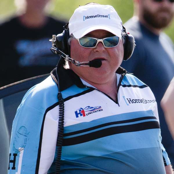
Crew Chiefs come to their positions in various ways – some are crewmen that have worked their way up to the position, while some are ex-drivers. All have been involved in the sport for ten years or more and most Crew Chiefs in our teams today count their experience in decades. Mike Hanson (below) has been a driver, Crew Chief and boat builder for decades and is one of the most successful Crew Chiefs in the sport.
The radio man is the eyes and ears of the driver while he is on the course. The radio man will almost always be either the Crew Chief or another driver, and their job is to keep the driver abreast of critical information necessary to run the race. He will communicate timing marks, the positions of the other boats, lane information, penalty calls, etc. – all of which makes him almost as important as the driver in the overall scheme of the race.
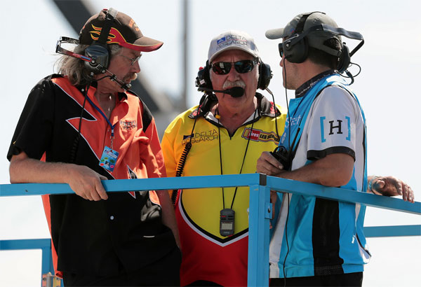
All the radio men from every team racing in each heat are gathered together in the “corral”, which can be a spot on the pit tower, a man lift (or two) in the pits, or any area where they can have a good view of the course. An H1 Unlimited official is also present in the corral to pass along any calls that are made during the race to the radio man for the offending boat.
THE BOAT
A modern Unlimited Hydroplane is the world’s fastest circuit racing boat, capable of speeds in excess of 200 mph. It represents the product of over 100 years of evolution in race boat design and incorporates the most powerful engines, most advanced construction techniques and the best safety systems available in boat racing today.
All Unlimited Hydroplanes are a “three point” design, meaning they are designed to only touch the water at three points when racing: at the rear of the two front “sponsons” (the projections of the hull in front of the driver cockpit), and the propeller at the rear of the boat. “Runners” under the sponsons and “shoes” at the rear of the boat are generally all that touch the water during race conditions.
A modern Unlimited is made of aluminum, steel, fiberglass, carbon fiber and graphite composites, and weighs a minimum of 6750 pounds in race trim. The boats are between 28 and 32 feet long, 12 to 14 1/2 feet wide and about seven feet from the bottom of the rudder to the top of the rear wing.
Driver safety is paramount in the design and operation of an Unlimited, so the boats have a number of systems designed to keep the driver safe in the case of an accident. The fully enclosed cockpit is the primary safety feature, incorporating a full interior roll cage that is bonded to the cockpit shell to maintain the integrity of the driver area. The windows are cut from the canopy of F-16 fighter jets, giving the driver ultimate protection, yet allowing him to see clearly.
Five point quick-release harnesses are used to keep the driver strapped into the seat and an escape hatch is built into the floor of the cockpit to allow the driver to escape if the hydroplane flips and lands upside down.
Every driver is required to wear a certified helmet and a HANS device for head and neck protection. He also wears a mask that incorporates an on-board air supply that allows him to breathe in case the cockpit fills with water, but also lets him communicate via the onboard radio.
Watch some of our drivers help explain what makes a hydroplane work:
Water is water, right? WRONG! Although we race on rivers, lakes and bays all over the world, our teams take a very different approach to racing on fresh water vs. salt water. This is due to the makeup of the water itself, the design of the boats and the power source – turbine or internal combustion engine.
Fresh water has no adverse effect on our boats or engines and there are no special precautions or setup changes necessary when we race on fresh water, but planning for salt water is dramatically different. When salt is dissolved in water, as it is in ocean water, that dissolved salt adds to the mass of the water and makes the water denser than it would be without salt. Because objects float better on a dense surface, they float better on salt water than fresh water. This means our boats and propellers act differently in salt water, so our teams have to take this difference into account when setting up the boats and choosing props. It also means that this dissolved salt is in every droplet of water that is ingested into our engines when we race.
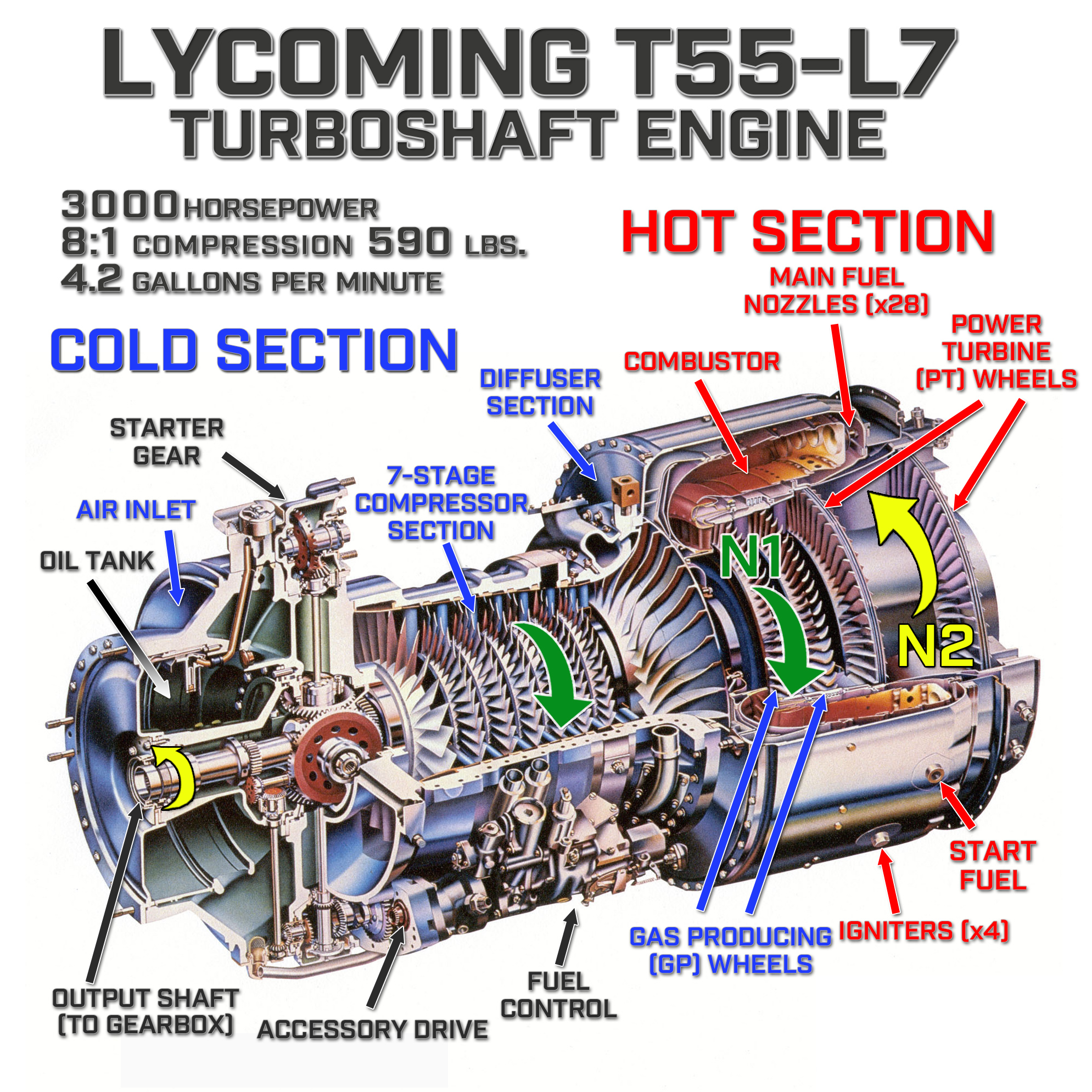
All boats that use the Lycoming T-55 L7 turbine engine have a MUCH different set of circumstances to contend with, and a little background on these engines helps put this difference into perspective: Turbine engines are actually very simple, and basically operate as a very large air pump: feed it fuel and air then add a spark and it will run very reliably and churn out huge horsepower until it runs out of fuel. Due to their design (and their original mission as the powerplant for the Army’s Chinook helicopters), they are able to take in large amounts of fresh water along with the air and still operate – as they would flying through a heavy rainstorm, for instance. The water simply gets vaporized in the combustion process and the engine continues to operate.
Although it’s possible to drown a turbine engine by ingesting extremely large amounts of fresh water, it’s almost unheard of to damage the engine as a result. This is definitely not the case in saltwater races! Even small amounts of salt water can cause catastrophic damage, so teams will do all they can to avoid getting saltwater into the engine.
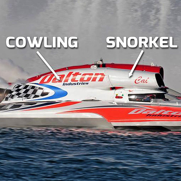
When leaving the dock and getting on plane, all hydroplanes send up spray in front of the boat, and all turbine teams use a “snorkel” extension on the cowling and even moveable flaps in the snorkel to help prevent this spray from reaching the engine. Now also keep in mind that each boat leaves a 300 foot long wall of water behind it, and with 6 or 7 boats on the course you’ll quickly see that avoiding taking in water at a salt water race is not easy.
Once salt water enters the engine, the water gets vaporized, but the salt that is contained in the water remains and builds up on the turbine blades. Even though this buildup can be measured in thousandths of an inch, it effectively changes the compression ratio of the engine (normally around 8:1), causing “pre-ignition” that is very much like increasing the timing or compression ratio in an internal combustion engine, resulting in very large backfires that will shoot large flames out of the back of the engine. Left unchecked, it can do severe damage to the turbine blades and the engine itself.
All turbine teams will usually “de-salt” their engines with special chemicals and you may notice them spraying their hoses directly into the engine inlet when they run the engines on the trailer at salt water races – this helps break down the salt buildup on the turbine blades.
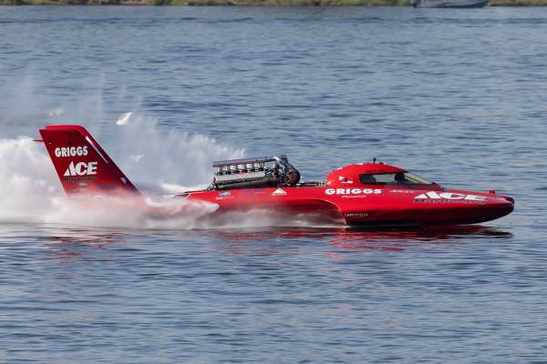
The twin-turbocharged V-12 Allison in the U-3 Cooper Racing entry doesn’t really care what water it’s racing on – it pumps out 3,000 HP whether it’s racing on fresh water or salt water, and this is the reason you will not see a cowl or “snorkel” on this boat during any race event – it doesn’t care what type of spray it’s breathing.
Additionally, due to the density of saltwater, there is more for the propeller to “push” against, which leads to more propelling force applied per revolution and consequently more speed. All current Unlimited competition speed records have been set on saltwater, with the current qualifying record of 173.384 mph set at San Diego, California in 1999 and the competition lap record of 166.221 mph being set at Pearl Harbor, Hawaii in 1992, both being set using unlimited fuel.
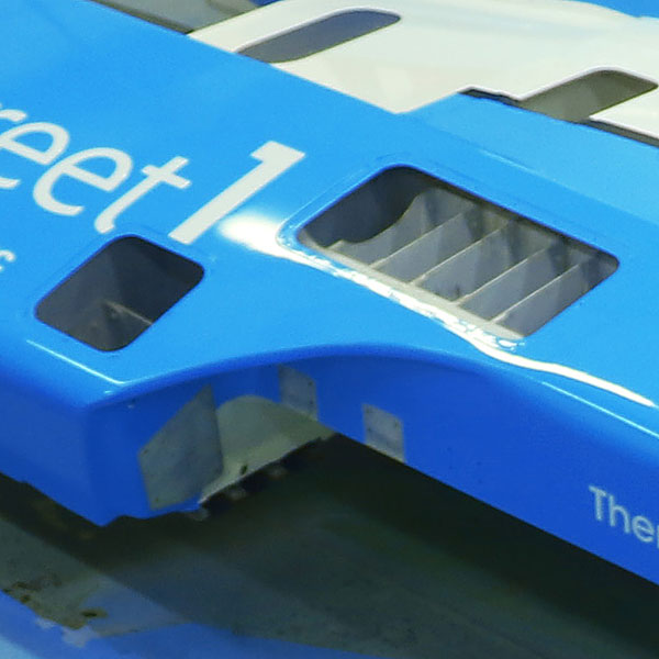
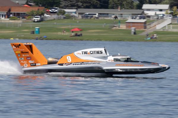
The large “cowling” behind the driver cockpit on all turbine-powered hydroplanes functions as an aerodynamic device and as a “scoop” to funnel intake air to the engine. The rear of the cowling is vented to allow for excess air to pass through so as not to trap air that would otherwise slow the boat down. All current Unlimited hydroplanes that use turbine engines have cowlings:
The U-3 Cooper Racing entry uses the V-12 Allison aircraft engine and is currently the only hydroplane that does not use a cowling:
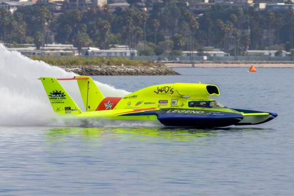
All teams run only the large rear cowling during races run on fresh water lakes and rivers , but saltwater and turbine engines do not mix well at all! During saltwater races, an additional extension to the cowling (known as a “snorkel”) is used to prevent saltwater from being ingested into the turbine engine – shown below above the cockpit lid of the U-11 Miss Legend Yacht Transport. Some teams fit a moveable door to the front of the snorkel which helps prevent saltwater from being pulled into the engine during the time when the boat is getting on a plane and sending large plumes of water into the air in front of the boat.
J. Michael Kelly’s cowling came loose during the 2019 HomeStreet Bank Seafair Cup race, getting snagged on the rear wing. He finished the race with a cowling borrowed from the U-7 team.
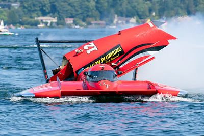
The sponsons (sometimes called “Canoes” when molded in one piece that incorporates the sponson, chines and air trap) are the large outboard structures that the hydroplane rides on when getting up to speed, then skips on while running at full speed. The bottoms of the sponsons have what are called “Runners” built into them that have specific design details (generally stepped surfaces) that each team will modify in order to help the boat go faster.
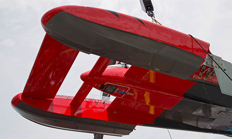
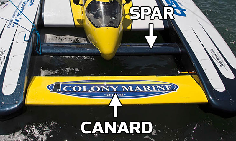
Sponson design and rigidity has a lot to do with the boat’s handling characteristics. The sponsons are glued or bolted to the “Center Section” of the boat (the main hull/engine bay/cockpit) and are further strengthened with the “Spar” – a steel beam that runs through the cockpit and ties the sponsons together. The spar is the non-moveable horizontal structure behind the canard.
All Unlimited hydroplanes have different designs for the left and right sponsons. Since the boats turn left and always present the right sponson to the outside of the turn, the right sponson is wider than the left and has a much gentler slope on its outside edge to help the boat skip over the waves. Most boats also have design details built into the inside edges at the front of the sponson that helps control the amount of water that splashes onto the windshield when running at lower speeds. These details are not so important now that the minimum running speed has been increased to 80 MPH.
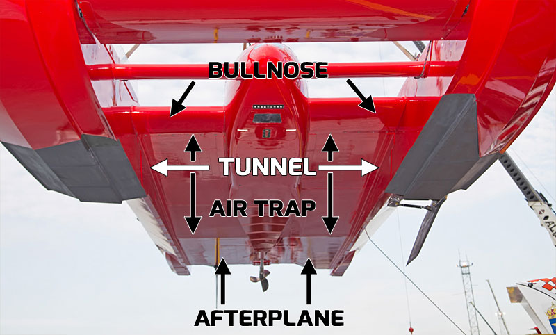
All modern Unlimited Hydroplanes incorporate a “Tunnel” under the boat that traps air as the boat reaches racing speeds, using the air pressure trapped in the tunnel to lift the boat and allowing it to reduce drag by flying across the water rather than plowing through it.
The tunnel is formed by the inside edges of the sponsons and incorporates an “Air Trap” that has a varying contour that is taller at the front than at the back. The Air Trap compresses the air as it travels under the boat and provides lift on the hull.
The forward edges of the Air Trap have what are called “Bullnoses” on each side of the cockpit that can be changed, with different contours or lengths to further fine-tune the amount of air that is fed to the Air Trap to help adjust the center of pressure.
The flat area aft of the Air Trap is called the “Afterplane”. The Tunnel width and length, along with the Air Trap angle and other design details all help contribute to the overall handling characteristics of the boat and are unique to each hull – what works on one design is certainly not guaranteed to work on another.
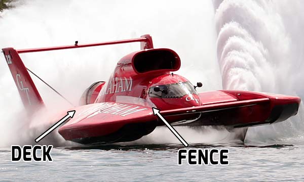
The deck is a structural component of the boat that forms the top of the hydroplane and is generally made of a sandwich of various composite materials. Over the course of the season, it is not uncommon for the deck to crack or split due to the tremendous forces exerted on the boat, and if this becomes severe or if there are cracks in critical areas, the team will replace it in the offseason.
The deck has a multitude of hatches (generally made from the pieces of aluminum) that give access to the various components that are located within the hull, such as steering cables, rudder linkage, fuel tank, fuel and cooling lines and other items.
The deck also has a gentle convex curve from front to back, which if looking at the hydroplane from the side, forms the upper surface of a wing with the bottom of the hydroplane basically flat. This helps generate aerodynamic lift.
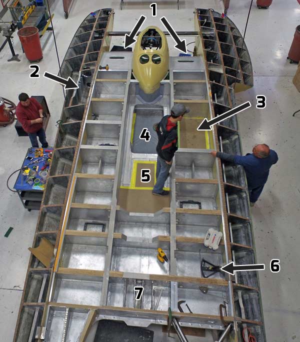
As the new for 2018 Miss Madison was taking shape, we took this image that shows what lies beneath the deck of a modern unlimited hydroplane. The entire structure is crisscrossed every 18-24″ with composite or aluminum sandwich braces in order to make the entire structure as rigid as possible, and some areas will have more structure added than is shown here.
Some highlights:
1: Bullnoses – Here you can see the left and right bullnoses are different lengths, which will be further fine-tuned with the additional of the outer bullnose shells. These will help determine how much air the boat “scoops” to feed the air trap underneath the boat.
2: Skidfin box – In this image, the additional braces that will make up the skidfin box are not yet added. When the boat is done, this area will be full of high-strength braces and brackets in order to withstand the extreme stresses the hydro will endure when cornering.
3: Fuel cell: The fuel cell will hold up to 50 gallons of Jet A in a rubber bladder full of material designed to minimize sloshing.
4: Engine bay: The engine and gearbox will fill this area, and will be mounted as low as possible in the hull to lower the center of gravity of the boat.
5: Shaft log: The shaft log is where the long shaft exits the hull. It transmits the output of the gearbox to the propeller.
6: Rudder quadrant: The steering cables engage the rudder quadrant that transmits steering input to the rudder.
7: Strut: The strut holds the propeller shaft (short shaft) and is mounted in this area underneath the boat. In order to keep the strut as solid as possible, the area it mounts to has additional bracing installed.
Since the top of the hydroplane forces air to travel farther than the air that passes under the bottom, at speed the boat generates lift in almost all directions, including while turning. The fence is a device that is made of plexiglass and is bolted to the inside of the right sponson and is designed to “spoil” the air that passes over the deck when the boat is turning, minimizing the lift that the right sponson can generate.
In the right conditions, you can see the effect of the fence on the air passing over the hydroplane – in Madison during a rainy day, the U-12 Graham Trucking shows how the air is affected by the fence, here forming vortices as the boat slices through the humid air:
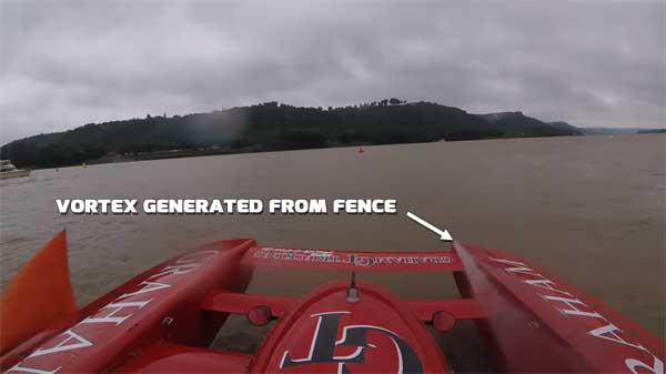
The canard, or front wing is controlled by the driver’s left foot, allowing him to raise or lower the wing while running to more easily fly the boat and also help eliminate flips. This works by pushing the rear edge of the canard down to create lift and raise the nose of the boat, or raising it to lower the nose of the boat if it gets too high and is in danger of “blowing over”. The driver will also manipulate the canard in the turns or when rough water and windy conditions persist.
The pedals are connected to the canard with a cable & pulley system. The cable attaches to an arm that connects to the pivoting shaft that the canard is attached to. Most teams us a series of linkages, springs or dampers to either make the pedal effort easier or to give more “feel” to the driver.
There are also limit stops to prevent the driver from putting in too much angle (especially in the “up” direction!)
The canard pedals are tied together and work opposite one another – as one pedal goes down, the other one comes up. In normal “neutral” running, the pedals are even, but once the boat starts gaining speed, the driver’s foot will always rest on the “down” pedal, ready to drop the nose at the first sign of a blowover.
The canard of the some hydros feature a unique “split” feature, allowing right and left halves of the canard to be adjusted independently, giving the driver more control over how the boat reacts to canard input.
The spar is a steel beam that ties the two sponsons together and to the cockpit. The spar is purely structural and has no aerodynamic function, but does normally have an aerodynamic covering.
Some older hulls have a canard system that uses a set of trailing “flaps” on a combination front wing/spar. The driver controls these flaps in the same way as the full canard, but this combination is not nearly as effective as a full-width canard with a larger range of motion.
The only hull still using this style of canard is the U-99, last raced in 2018 – in fact, this boat had flipped twice in the past at the Detroit race, and some think the lack of a full-width canard may have contributed to the boat “getting away” from the drivers:
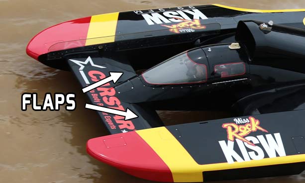
The rear wing is a very important part of the boat’s handling adjustments, as minute changes affect the running attitude of the boat. When setting up the angle of the wing, most teams use a digital bubble level, and fine-tune that angle to 1/10ths of degrees.
When the wing is adjusted properly, it helps control the ride height at the back of the boat, ideally allowing the prop to run with only one blade in the water during every revolution.
Here Jeff Kelly of the U-8 Miss Tri-Cities team adjusts the angle of the rear wing:
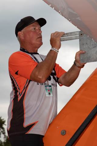
The rear wing also acts as a platform for our mandatory GoPro onboard video cameras during every heat of competition. The wing is mounted to what are sometimes called “tail feathers” or “uprights” which are trusses that support the wing and are covered with fiberglass panels that carry sponsor decals.
Another function of the uprights is to form a vertical aerodynamic surface, giving directional stability at the rear of the boat. The uprights are braced with support rods that tie the tops to the center of the transom. Occasionally, these can break, leading to the entire wing assembly leaning over or even breaking off completely. In the video below, you can see what happens when one of the struts that holds up the wing breaks.
At the Madison APBA Gold Cup in 2021, one of the struts holding the wing on the rear of the U-12 Graham Trucking broke, letting the rear wing assembly fall over and ultimately destroy the wing and both uprights. More importantly, the strut fell into the prop while the boat was running! Only by sheer luck did the prop not destroy itself, allowing Andrew to get the boat back to the dock:
The “non-trip” is part of the side of the boat extending from the back of the sponson to the transom, formed by a panel that is angled inward to the edge tunnel at the bottom, forming a sloping surface that allows the rear of the boat to more easily skip across the water while turning. It’s name comes from it’s function: designed not to “trip”, or dig in as the boat turns a corner.
The “shoe” is a device that is designed to assist in supporting the back of the boat while running, cutting down resistance. They have an angle of attack similar to the sponsons to lift while dragging. The shoes extend beyond the transom, and in most boats, the right side is much longer than the left.
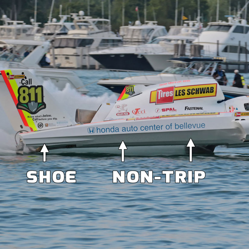
The transom on an Unlimited hydroplane is the short vertical surface at the rear of the deck and is a structural part of the boat, with the extremely stout rudder bracket bolted to the right side and the bottom mounts for the rear wing braces attached in the center.
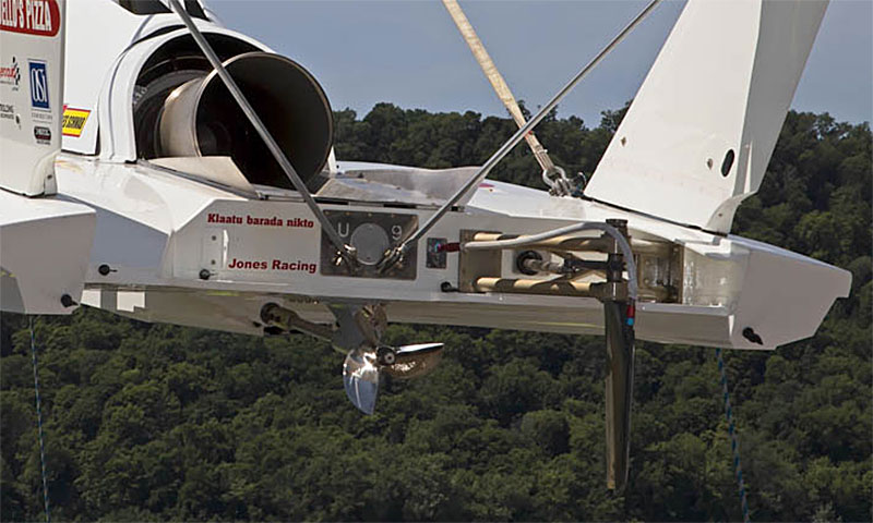
THE ENGINES
The turbine began taking over as the power plant of choice in the 1980’s as the piston aircraft engines became more scarce. Today, all unlimited hydroplanes except for the U-3 Go3 Racing entry use the Lycoming T-55 L-7 turbine engine. The T-55 L-7 was designed in the early 1960s and was first delivered for use in a CH-47B helicopter in July 1963. It was used extensively during the Vietnam War.
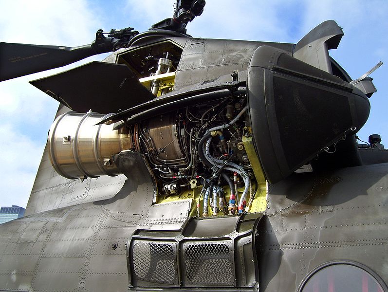
Although the engine may look complex, it is really very simple and operates on the principle of expanding gases that turn rotating vanes to produce power, and when compared with a piston engine, the installation of a turbine is quite simple.
A turbine is air-cooled, so there aren’t any water lines. The engines also have a self-contained oil system, so there is no need for oil lines. The only things connecting it to the boat are fuel lines, a battery, the throttle, and the cables that transmit engine speed and temperature readings.
All of the power of the engine goes to the prop – the exhaust nozzle only allows hot gases to escape – it does not help propel the boat.
There are only three ways to extract additional power from a turbine: 1) Increase the amount of fuel going into the combustor, 2) Increase the efficiency of the compressor by tightening the clearances between the rotors and stators, or 3) Adjusting a governor that limits the speed of the N2 turbine.
The fuel flow and N2 speed are governed by H1 rules. The turbines are regulated to 4.2 gallons of fuel per minute and 110% of manufacturer rated maximum N2 speed (output RPM).
The T-55 L-7 is extremely reliable, and in contrast to some piston engine designs, one engine can last an entire season with minimal maintenance provided it doesn’t encounter too much saltwater.
One boat (the U-440 Bucket List Racing entry) runs a Lycoming T-53 L-13 turbine engine. The T-53 is a smaller sibling to the T-55, with a smaller overall diameter and length, and making about 1500 HP in race trim. Its layout is very similar in to that of the T-55, but it has a 5-stage compressor (five sets of compressor blades instead of the seven in the T55 L-7) and two GP and PT wheels. The T-53 powered the US Army’s Cobra gunships.
In the Lycoming T55-L7 turbine engine, the air passes through a series of seven rotating blades and stationary stator vanes to become compressed (thus it is classified as a 7 stage compressor), then exits through a diffuser section into the combustor section, where it reverses direction and is mixed with jet fuel that enters the engine through 28 fuel nozzles.
The compressed air/fuel mixture is ignited in the combustor assembly. The resulting explosion of rapidly expanding gases then reverses direction and rushes from the combustion chamber towards two sets of fan blades. The fast-moving gases first pass through two N1 turbine wheels, which are called gas producing wheels or “GP” wheels.
Like blowing on a pinwheel, those gases cause the wheel to spin in a counterclockwise direction, which turns a hollow shaft that drives the blades in the compressor. The gases then pass through the N2 turbine wheels, which are called the power turbine or “PT” wheels. They cause them to rotate in a clockwise direction, which then spins the drive shaft that rotates inside the hollow center of the compressor assembly.
This output shaft exits the engine at the front end (where the air entered – towards the bow of the hydroplane), and a short shaft connects it to the gearbox, which then passes the engine power via the long shaft to the propeller.
The image below shows how the GP and PT wheels are connected and how the air flows through the engine:
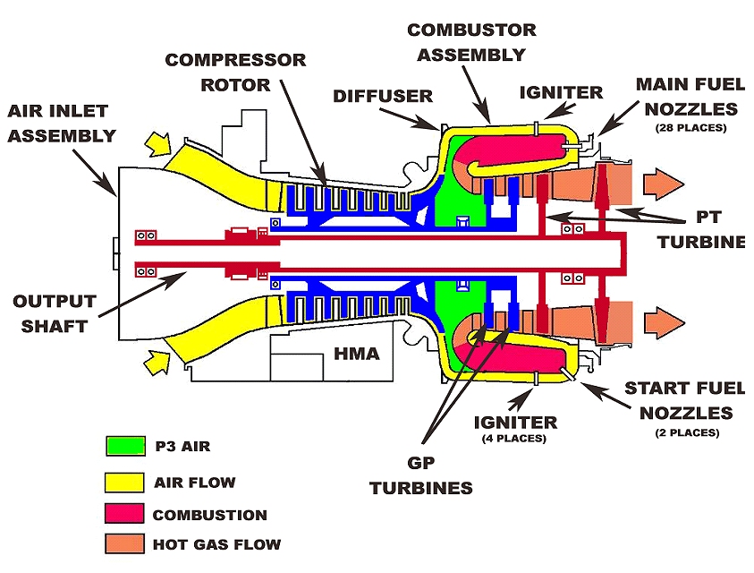
The entire power producing process is self-sustaining – as long as there is fuel to burn, the engine will continue to run. Once the engine is started, the only way to shut it off is to remove the fuel supply, which is done from the cockpit by the driver by shutting a valve.
In rare cases, this does not work, leading to some “interesting” attempts at getting the engine to shut off.
In the video above, at the Oryx Cup in 2011, Jimmy Shane’s U-57 would not shut off as he came back to the dock – the engine would not go below its idle setting, which kept the engine running and forced Shane to turn back out into the course.
Unfortunately, hydroplanes are very sluggish at low speeds and he ran directly into Brian Perkins. As the U-57 slowly forced Perkins’ boat back to the dock, crew members were forced to rip its cowling off to shut off the fuel manually.
In the clip below, Scott Raney, Crew Chief of the U-11 Legends Yacht Transport discusses some of the processes involved in the overhaul and dyno testing of the Lycoming T55-L7. Video courtesy of U-11 Unlimited Racing Group Racing / Edited by David Cormier.
While the majority of our Unlimiteds are powered by the T-55 L-7 turbine engine, there is one team that has gone a different route down the turbine engine path: the U-440, owned by Kelly and Sharon Stocklin. They have pioneered the use of the T-53 L-13B – the little brother to the T-55.
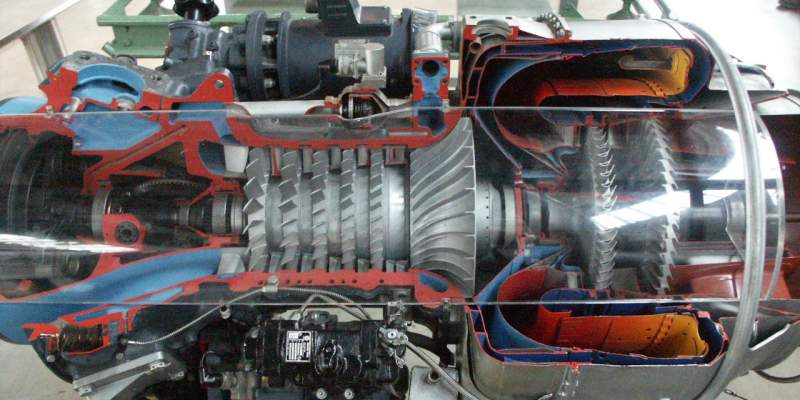
The image above shows a cutaway view of the T-53. Beginning at the far left is the intake section – the air enters this inlet and gets routed to the compressor section – the five rows of silver blades and vanes in the middle. Each row of blades gets slightly smaller and compresses the air a little more until it reaches the diffuser section, which is the ramped “pinwheel”-looking assembly at the end of the compressor section.
The diffuser routes the compressed air out and around the outer circumference of the “burner can”. As the air gets forced around the burner can, it eventually enters the combustion chamber – the area painted yellow-orange-red at the right, where fuel is added from a series of injectors. The fuel is ignited, which explodes and the resulting high pressure gasses are released out of the burner can directly onto the blades of the first two wheels, which drive the compressor section, then onto the two counter-rotating “PT” (power turbine) wheels, which drives a shaft that goes through the center of the compressor shaft and out the front of the engine to the gearbox.
The video below shows a cutaway version in motion:
While the T-53 is a gas turbine like the bigger engine, it is a scaled down version, with 5 compressor stages vs. 7 on the T-55. The rated horsepower is scaled down as well – 1400 horsepower vs. 2650. Of course, Kelly has made modifications to boost that rating substantially, and in its current state of tune in the U-440, the motor is pushing out close to 1700 horsepower.
As with all R&D efforts, when you increase performance in one area, you highlight weaknesses in others, and in the 440’s case, the gearboxes were not up to the task of transmitting the extra power made by the T-53. Kelly states “when we started making real power with this engine, we started eating gearboxes for lunch”. In successive races, the U-440 did not make it into competition due to gearbox failures. While somewhat discouraging and perplexing, the problem was finally solved by essentially redesigning the gearbox and using heavier duty components all the way through.
The U-440 will be driven by Brent Hall in 2023 and will still be powered by the little engine that could – the Lycoming T-53.
The very word Unlimited conjures up a vision of the biggest, baddest powerplants on the planet being shoehorned onto a boat and raced. There were no rules regarding power plants in the Unlimited class for the majority of it’s history, and for decades Unlimited hydroplanes were powered by internal combustion engines of various types, using many styles of automotive power plants and even outboards.
Most teams eventually settled on three different V-12 WWII aircraft engines: the Rolls-Royce Merlin, Rolls-Royce Griffon and Allison V-1710. Once available as surplus for as little as $350, the days of the V-12 were numbered when the turbine engine arrived on the scene due to scarcity of parts and high running costs. Immediately post-war, Allison engines were plentiful and very cheap, making them a perfect powerplant for what was becoming the very popular Unlimited class of race boats:
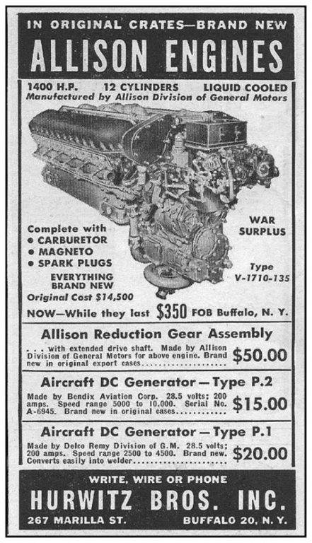
Today, there is only one team that runs the 1710 cubic inch V-12 Allison: the U-3 Racing Team owned by Ed Cooper of Evansville, IN.
The engine is turbocharged, using the exhaust gases to spin two very large turbochargers to force more fuel & air into the cylinders with methanol fuel injection, and a water injection system to help cool the intake charge. The team does not use an intercooler in this application. In this configuration, the engines produce upwards of 2,500 HP, allowing instantaneous acceleration with top speeds to match all of the turbine boats.
Beginning at the front of the engine bay, you see the very large oil tank that holds the gallons of oil needed to lubricate the massive engine.
Attached to a steel plate bolted to the front of the engine are the two very large turbochargers that feed the intake manifolds that extend up over the top of the engine. The turbochargers are fed by the exhaust stream that spins the turbos at very high speed, which in turn spins the intake impeller, forcing more air into the manifolds under pressure. The exhaust then exits via the short pipes on the outside of the turbos.
This intake pressure is regulated in two places: the waste gate and the overpressure valve. They both insure that if there is too much pressure in the manifold, these valves will open, dumping the excess pressure. Extremely high boost pressure will cause engine damage very quickly and is to be avoided at all costs.
Since gases under pressure heat up, the intake air fed to the cylinders is very hot. The U-3 uses water injection to help cool this charge. The water injectors are located directly in front of the turbo intakes and spray water directly into the turbo.
Watch the video to see this process in action – it’s pretty cool to see! Fuel injectors feed the methanol fuel directly to each cylinder, and the charge is fired by two high performance coils that generate the spark – one for bank.
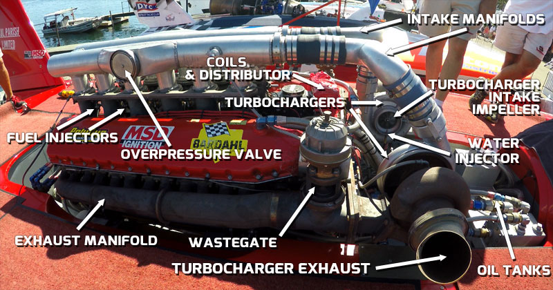
Ride along with the U-3 Go3 Racing entry to see and hear a full-race Allison V-12 in a modern Unlimited Hydroplane:
The fuel control for the T-55 turbine engine functions like a carburetor, metering the correct amount of fuel based on the various parameters it monitors. Fuel flow is currently regulated to 4.2 gallons per minute (GPM) and is monitored by the onboard data recorder installed in every boat during every timed run and during every heat of racing.
Because it a fully analog device (no electronics of any sort) and originally designed in the 1950’s, the fuel control can be very temperamental and difficult to fine-tune. One of the most valuable people on the team is the crew member assigned to dialing in the fuel control. He will be able to extract the most power out of the engine while keeping it under the mandated 4.2 GPM fuel flow rate.
H1 Unlimited rules dictate that fuel flow and engine RPM be monitored for violations. We also monitor speed via GPS to insure our boats don’t drop below 80 mph. We add a data recorder to each boat prior to each timing run and heat race to monitor these parameters and and log the critical data streams. These data recorders are installed on the engines using standardized connectors, sensors and wiring.
Prior to each qualifying attempt and heat race, a data logger is installed in every boat, then removed when the boat returns to the dock and taken to the “tech truck” where the data is read to determine if any of the monitored parameters were exceeded.
If no violations are found, it’s a “clean run” and all speeds and finishes stand. Fuel flow and N2 violations may result in monetary fines, or if a violation is determined to be “flagrant”, it will void a qualifying speed or cause the loss of points or even disqualify a boat from the heat in which the violation occurs. Speed violations (going below 80 MPH for more than the allowed 5 seconds) will result in disqualification. For engine RPM, a violation occurs when the 110% N2 limit is exceeded for more than three seconds or the 115% N2 limit is exceeded for more than one second. More than two violations will be considered a flagrant violation and will result in forfeiture of points and may result in disqualification:
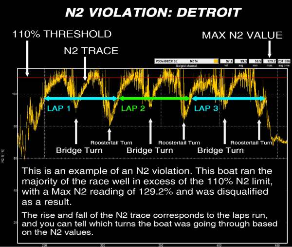
The engines are limited to 4.2 gallons per minute fuel flow. A violation occurs when this limit is exceeded for more than three seconds, and up to two violations per heat will incur a $100 fine for each violation. More than two violations will be considered a flagrant fuel violation, and will result in forfeiture of points and may result in disqualification.
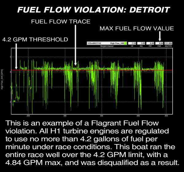
Just like NASCAR, Indycar and F1, H1 Unlimited racing is a data-driven sport. The onboard data recorders or “Black Boxes” can monitor many different parameters – these are only limited by the number of sensors the team wants to install on their boat. The data is recorded while the boat is running, then offloaded when the boat returns to the dock – as yet, there is no real-time data collection in H1 racing.
Crew Chiefs and drivers will usually study the data immediately after each run to determine how the monitored systems performed and what changes need to be made prior to the next heat. The driver can also compare his impressions of the run with the data – and the data doesn’t lie!
Most teams monitor many more data streams than the fuel flow and N2 RPM that H1 regulates, and the linked video shows how this data can be put to use. Seph Parshall, then of the U-9 Jones Racing team (now H1 Tech Inspector), produced the video below showing the various data streams overlaid on both in-cockpit and rear tail footage.
Starting at the left side, you see the large speedometer, paired with the FUEL FLOW and EGT (Exhaust Gas Temperature) dials to the right. N2 RPM percentage is the bar graph below the speedometer.
Next comes CANARD angle and THROTTLE percentage, with a moving G METER and GPS moving map on the right side.
You can also see the various gauges that the driver monitors in real time and the digital countdown clock installed on the steering wheel.
Using all of this data, the team can determine how the engine is running, how the driver is controlling the boat and boat is responding to all of the inputs.
A Rotor Burst Protection System, or “RBPS” (the black fabric wrapped around the “hot end” of the engine) is in place around the “hot end” of the engine to contain the fragments in case of a catastrophic failure of the turbine’s power rotor.
Even though the hot end has a thick metal shroud to help contain these fragments, very high-speed shrapnel could very easily tear through this shroud and through the bottom of the boat, or when testing could very seriously injure or kill anyone standing directly beside the engine.
The RBPS blanket is made of ballistic materials and is a mandatory piece of safety equipment.
The video below shows how violent engine explosions can be and how the RBPS system contains the shrapnel when it happens. J. Michael Kelly’s U-8 Miss Tri-Cities broke the main shaft in the turbine, which led to the total loss of the $100,00+ engine:
Turbine engines are basically a very simple system: spool it up, feed it fuel, then add a spark and the engines will pump out 3,000 HP until it runs out of Jet-A. They do not require electrical power of any sort to run, only to start. This makes the electrical system in an Unlimited hydroplane very simple.
The igniters (spark generators that light the fuel during startup) on the Lycoming turbine run on 24 volts DC and so require a 24 volt battery (two 12 volt batteries run in series) to run them.
However, the starters require 48V, so an additional two 12V batteries are added and through a series of relays and solenoids (pictured below), all the batteries are temporarily wired in series to provide the 48V required. The relays and solenoids are usually mounted in a compartment behind the cockpit.
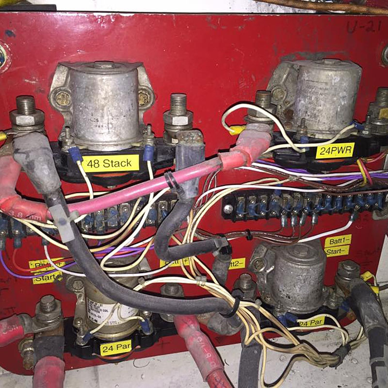
The batteries are generally stored in a sealed box or boxes and are stored in a compartment under the deck and may or may not be removable.
There is no charging system on the boat, so the batteries need to be charged occasionally during the race weekend. Teams will keep a close eye on battery condition, as a marginal battery will jeopardize their ability to race.
The igniters are basically a spark generator that you may be familiar with in the barbecue you cook your burgers on – it’s the same principle, only with much stronger sparks. In fact, if you’re close enough to an Unlimited as it’s starting, you may hear the “tick-tick-tick” of the igniters right before the “whoosh” as the engine fires.
The remainder of the systems on the boat run on 12 volts, such as the gauges or digital dashboard, emergency beacons or other data devices.
The gearboxes used in the turbine-powered boats are under tremendous stress, taking the 3,000 horsepower output of the engine and sending it to the prop, so the gearbox oiling system has to be of very large capacity with a high-performance filtering system in order to keep the gearbox supplied with clean lubricant.
A gearbox oil pump pulls lubricant from a large tank situated ahead of the engine. These tanks usually hold 4-5 gallons of lubricant and all have a reusable filter element to filter out contaminants such as metal debris. Most tanks incorporate some type of cooler as well, with the lubricant being cooled by water picked up from the inlet pipe attached to the back edge of the rudder.
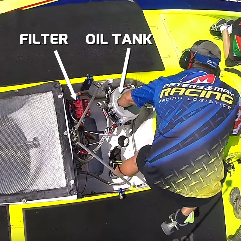
All of the Lycoming T-55 L7 turbine engines run on “Jet A” fuel, which is close to kerosene in consistency. Based on the regulated rate that the turbine engines can consume fuel (4.2 gallons per minute) and the length of each heat race (launching from the dock, the “milling” period before the start and up to 5 laps that the boats will race), means that the boat needs to carry 40-50 gallons of fuel to guarantee they will have enough to complete each heat. The U-3’s twin turbocharged V-12 Allison runs on methanol.
The fuel is stored in a rubber bladder that is stored under the deck and is connected to the engine with lines that run from the bottom of the bladder to the fuel pump and into the engine. The bladder is usually filled with inert foam or plastic balls to prevent sloshing as the boat is cornering, allowing more uniform fuel delivery.
THE RUNNING GEAR
The turbine engine’s output is hooked to a “gearbox” that sits between the engine and cockpit. All gearboxes for turbine-powered boats are a “V” design, meaning they take engine output from the front of the engine (connected with a very strong short shaft), then the gear set reverses this output to the propeller via a “long shaft” that exits the boat through a “shaft log” that has seals to keep water from leaking around the shaft into the engine bay.
The gearbox has a single adjustable gear ratio that reduces the engine speed to the appropriate output shaft speed to make the propeller work most efficiently. In contrast to most race cars, the driver cannot change this ratio – it is a laborious process that will usually take the crew an hour or more to change. The gearbox ratio will be determined using course length, propeller pitch and preferred lane choice as factors.
On the U-3 Cooper Racing entry, the V-12 Allison engine feeds a gearbox located directly off the the rear of the engine. This gearbox speeds up the propeller and passes the output directly to the prop.
In the image below, at the 2013 Bill Muncey Cup in San Diego, Mark Evans’ U-57 FEDCO hydroplane lost a blade on the propeller, and the forces exerted due to the unbalanced prop were so great that it broke the strut completely in half (the strut is the bracket that holds the “short shaft” at the rear of the boat). With the short shaft mount gone, this allowed the “long shaft” to spin unsupported.
The long shaft unbalance now ripped out the “shaft log” (the sealed section where the long shaft exits the bottom of the boat). Since the long shaft is rigidly connected to the gearbox, and there was now 6 feet of this hardened steel shaft swinging wildly around under the boat, the only thing left to resist that force was the output gear and bearing in the gearbox, and they lost the battle.
As you can see, the gearbox ended up completely split in half, even breaking the mounting struts holding it to the boat! From what may have started as a tiny crack in the propeller ended up doing $50,000 + worth of damage in the blink of an eye…
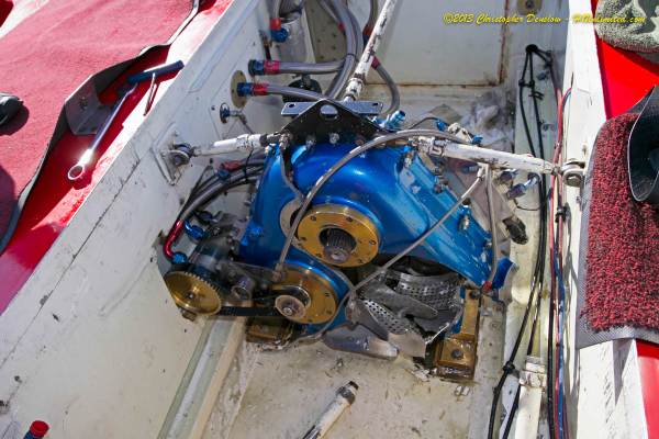
The “long shaft” connects to the gearbox and transfers the engine output through the bottom of the boat through the “shaft log” that seals the shaft to prevent leaks. The long shaft connects to the “short shaft” with a “coupler” that allows the short shaft to be removed quickly. The short shaft rides in the “strut” and has the propeller connected to the end of it, held on with a very large nut.
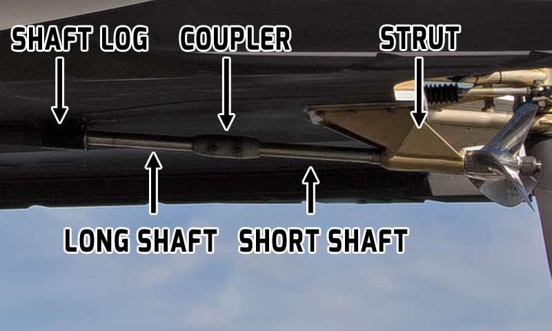
Most teams have multiple short shafts with different propellers already mounted, giving them the ability to quickly change for testing or for different race conditions.
Of all of the parts of an Unlimited hydroplane, perhaps the most important and most mysterious is the propeller, because no matter how much horsepower your engine makes, the prop is the part that converts that power to speed. The 3-bladed prop on a modern Unlimited creates the distinctive “roostertail”, raising literally tons of water into the air for up to 300 feet behind the boat. The propellers used on the Unlimiteds are limited by rule to 16″ in diameter and can cost over $15,000!
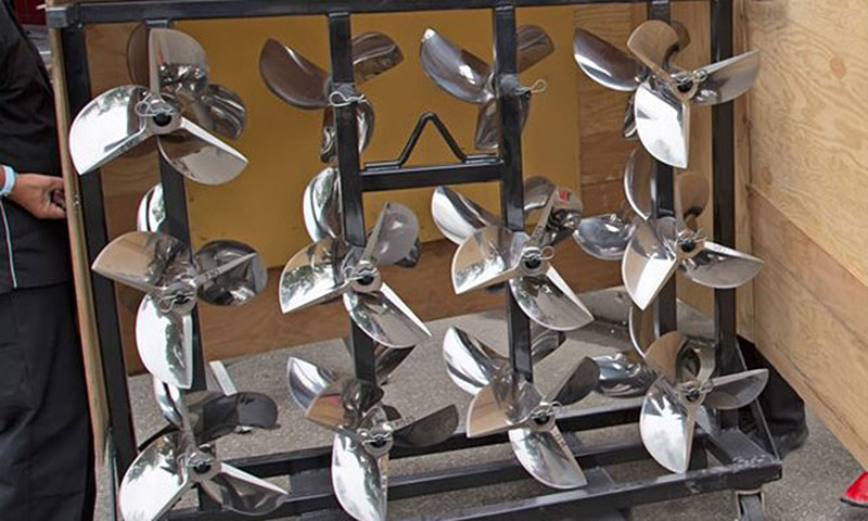
All teams have multiple propellers that they can use to help the boat go faster, pull harder or handle better. The best props are very thin – only thick enough to keep their shape and stay together for a short period of time (usually less than 100 minutes total time before they are “timed out”, meaning that it costs $150 PER MINUTE of use on the boat). As you can imagine, there is a LOT of experience, knowledge, material science and mathematics involved in building a prop, and those that make the best ones keep their information a closely guarded secret. According to highly regarded propeller manufacturer Kelly Stocklin, owner of the U-40 and U-440, each prop requires over 60 hours of machining on his CNC mill, then many more hours of final work before it is ready to be mounted on a hydroplane.
During manufacture, the propeller is usually cut to a slightly smaller diameter than the 16” allowed due to the fact the forces that act on the prop will, over time, actually bend the blades and the propeller will “grow” in diameter. If the prop was manufactured to the allowed spec, it would become illegal before it has timed out.
Different props are chosen for use based on course length, turn radius, course conditions, number of boats in the heat, lane choice, gearbox ratios and a host of other considerations. The propeller chosen can help control the boat’s attitude at speed, and if the boat ride is tuned properly, at racing speeds the propeller typically has only one blade in the water at a time!
Since the prop is razor sharp and very thin, they can be prone to cracking and have a very limited lifespan. Turning at over 9,000 RPM while racing, they usually last no more than two hours before they are considered a “ticking time bomb”, ready to shed a blade while running. If this happens, the resulting vibration will usually tear the back half of the boat apart.
In order to minimize the chances this will happen, after every heat, the crew person in charge of the prop will remove the short shaft with the propeller attached to it and inspect it for any damage that may have occurred during the run. Most often, there is no obvious damage and the prop will only require light sanding to the leading edges, but that is not the end of the inspection.
A more thorough inspection uses fluorescent dye or magnetic particles to make sure there are no hidden flaws that may develop into cracks that will eventually break the prop and destroy the boat. In each team’s pit, you will see black tents like in the image below (with Randy Roe from the U-11 team inspecting), where the prop is coated with dye, then viewed with a black light that will help highlight any flaws. This is a painstaking process, requiring the crew member to stay inside a very hot tent while he inspects each and every square inch of the propeller for damage. Only after it has passed the inspection process will it be put back on the boat.
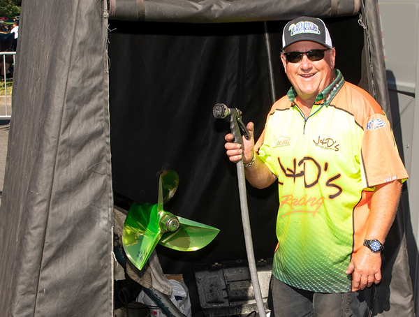
Even if the team does all of the maintenance and inspections of their props, other factors can doom the prop and the boat. If the boat hits debris, such a floating branch or log, it may not cause extreme physical damage to the prop, but it can bend a blade and unbalance it to the point it will end its life. Even the very metal forgings that form the genesis of every prop can be flawed – for instance, in Heat 2 at the 2022 San Diego Bayfair, Dustin Echols was running a prop that had done only 5 laps when a blade broke, sending the blade through the left upright and unbalancing the prop shaft, doing extensive damage to the back of the U-40:
On detailed review of the remains of the broken prop, Kelly Stocklin identified a flaw in the metal forging that formed the blank for the prop. It illustrated that even when you do everything right in the care and feeding of your props, there are a myriad of things that can affect their life expectancy!
To get an idea of what these amazing works of mechanical art do in the water, watch this clip, shot in slow motion form the back of the U-8 with J. Michael Kelly driving at the 2022 season-opening test in Vancouver, WA. Kelly had the boat flying at an almost perfect attitude, as evidenced by how clearly you can see the propeller turning, without a lot of water splashing around it. There are portions of this clip that very clearly show that only the bottom half of the propeller is actually touching the water, which is the ideal scenario, and you can clearly see each blade’s “cut” through the water as the roostertail starts to form.
Also note also how little of the rudder is actually in the water during straightaway runs – only about half of it is in the water at any time!
The skidfin (sometimes called a “turning fin”) is a large flat steel plate with a razor sharp leading edge that weighs up to 400 pounds. By rule, it has to be completely flat, with only .050″ variance for concavity. It is very rigidly attached to the left side of the boat with a very strong bracket and many very stout steel rods. It is connected to the strongest structure in the entire boat – in fact, the boat is essentially built around the skidfin mounting points, with that portion of the boat containing much more reinforcing structure than any other area.
Considering that the boat weighs almost 7,000 pounds and is subjected to 5-8 lateral G’s in every corner, the skidfin and its components have to withstand the pulling power of up to 50,000 pounds up to 10 times during every heat, which means everything associated with it needs to be EXTREMELY heavy-duty!
In this view of the U-1 Miss HomeStreet Bank, the internal structure in the skidfin area under the deck is evident:
Multiple ribs tie the outer portion of the sponson where the skidfin will attach to the center section, helping to transfer the tremendous loads generated during cornering throughout the structure of the hydroplane. If the skidfin were only attached to the sponson, it would very easily tear the sponson off the boat.
The skidfin has evolved over time, from being almost non-existent or extremely small on the older hydros, to the giants we see now. There are many different sizes and shapes of skidfins on our boats, and these can be changed to suit the course we are racing on, but per our rules they are all made out of a single piece of completely flat, extremely high-strength steel. In the past, curved skidfins were tried, but outlawed.
The purpose of the skidfin is to give the boat a pivot point around which to turn through a corner at 200 MPH, and to “hook” the boat into the water through the turns. Since our rudders are relatively small in comparison to the size of the boat, they don’t become effective until the boat reaches speed.
However, even at speed the driver could turn the rudder to the left and the boat would simply skip along almost straight if there were nothing to give the boat a pivot point to increase the effectiveness of the rudder. With a skidfin in place, once the rudder turns the rear of the boat to the right (pointing the nose of the boat left), the massive skidfin bites into the water and allows the boat to carve through the turn MUCH faster than if it were simply skipping across the top of the waves.
With water being 800 times more dense than air, adjustments to the skidfin are CRITICAL to the handling of the boat, and are measured in fractions of an inch. This is due to the massive size of the skidfin – imagine dragging something almost as big as a door through the water at 200 MPH with the leading edge pointed a different direction than you want the boat to go – even if you were off by a tiny bit, the drag would increase so much that the boat would go where the skidfin points, regardless of where the driver wanted it to go.
The angle of the skidfin in the left-right axis (toe angle) is adjustable and is the setting that has the most impact on the performance of the boat (and the driver), since it determines whether the boat will track straight or will pull to the left or right on the straightaways. If this setting is not correct, it can take all of the driver’s strength simply to steer the boat straight, resulting in extreme driver fatigue and scrubbing off speed at the same time. The skidfin is usually set up to be absolutely parallel to the “air trap”. The teams will use a long straight steel bar, laser or a string attached to the inside flat surface of the skidfin and measure the setting at the rear of the boat – some 8-10 feet away, and the adjustments are made in 1/32″ of an inch! To put this in perspective, if the skidfin is “toed out” or toed in” more than even 1/8″, it will make the boat almost undriveable!
In some cases, getting this measurement wrong can have extreme consequences. U-11 Crew Chief Scott Raney relates a story of experimenting with skidfin settings on the “Tide” boat with Nate Brown driving at the 1993 Tri-Cities race: “We tried toeing the fin in (pointing the leading edge toward the center of the boat) just 3/32” to try and make the boat handle better, and Nate only made it 2 laps before the boat “rode up” the skidfin and flipped!”:
The skidfin is also angled, with the bottom of the fin closer to the boat than the top (skidfin angle). The angle helps determine how much “bite” the skidfin exerts while traveling through a corner and can be adjusted with different wedges or spacers between the fin and the mounting bracket. A steeper angle will help keep the left side (inside) of the boat lower in the water while turning, making the boat corner flatter so as not to allow the right sponson to dig into the water, which increases drag and scrubs off speed. If the angle is set too shallow, there is the risk of having the boat “unhook” while cornering which can result in the boat jumping outward into another lane and can be disastrous if there is another boat there already!
Lastly, the skidfin can be moved forward or backward on the mounting bracket and is used to fine-tune “oversteer” and “understeer” – the way the boat responds to steering wheel inputs from the driver. If the boat is set up to be “neutral”, the driver will steer into a corner and the boat will follow his intended arc without any additional steering input.
If the driver steers into a corner and has to keep turning the wheel to the left in order to maintain the same relative arc, this means the boat is understeering or “pushing”. To combat this, the skidfin can be shifted rearward on the bracket, which moves the pivot point more to the rear, making the rudder more effective in turning the boat.
Conversely, if the driver enters the turn and has to continually adjust his steering to the right to maintain the same arc, this means that the boat is oversteering and the skidfin can be moved forward to counteract it.
All skidfin adjustments can have HUGE consequences both in speed and safety, and it’s easy to see that in order to be fast, everything needs to be set up perfectly. When it’s done right, the boat will be fast and the beautiful wall of water the skidfin throws up in a corner is one of the most spectacular sights in boat racing, reaching heights of nearly 50 feet and extending for 7-10 boat lengths behind the boat.
The image below shows the brackets and rods that hold the skidfin to the boat. All bolts and rod ends must be new, “first use” items to prevent any recycled materials from being used in this critical area.
Due to the extreme strength of the bracket and structure surrounding the skidfin, when an Unlimited hydroplane flips, the skidfin bracket is what is used to recover the boat:
Lastly, when things go wrong with the skidfin, the consequences are disastrous: In Heat 1B at the 2010 APBA Gold Cup in Detroit, the skidfin tie rods on JW Myers’ U-37 Miss Peters & May hydroplane broke as he was entering the Roostertail Turn, sending him headfirst into the seawall in front of the Roostertail restaurant. Although the boat was destroyed, Myers came away from the accident with only a broken left foot.
This incident shows how vitally important the skidfin is – without it, the boat has virtually no directional stability and will follow essentially a straight path with very little ability to turn due to the very small area of the rudder.
The rudder is a very thin, razor sharp piece of high strength steel located on the right rear of the boat, attached to the transom with a very stout bracket and controlled with a steel cable via pulleys from the steering wheel. There is no power steering on our hydroplanes.
The rudder bracket extends the rudder well past the end of the boat in order to gain more leverage for turning the boat.
Although the rudder is very thin (and on a normal boat would be very ineffective), in conjunction with the skidfin that acts as a “pivot” on the left side of the hydroplane and with the leverage the rudder gains from being extended from the transom, it becomes very efficient in this application, but only at race speeds. At slower speeds, the rudder is not nearly as useful and makes low-speed maneuvering somewhat challenging.
The rudder normally has a water pickup tube that supplies cooling and lubrication water to the engine, gearbox and output shaft.
The image below shows the rudder steering quadrant that works to translate the steering wheel rotation into rudder movement. The large rod that exits the transom is attached to the rudder arm. This rod can be attached to the steering quadrant and rudder arm in different places to change the effective steering ratio. The damper helps minimize “rudder flutter”, a condition that can literally rip the rudder off the back of the boat.
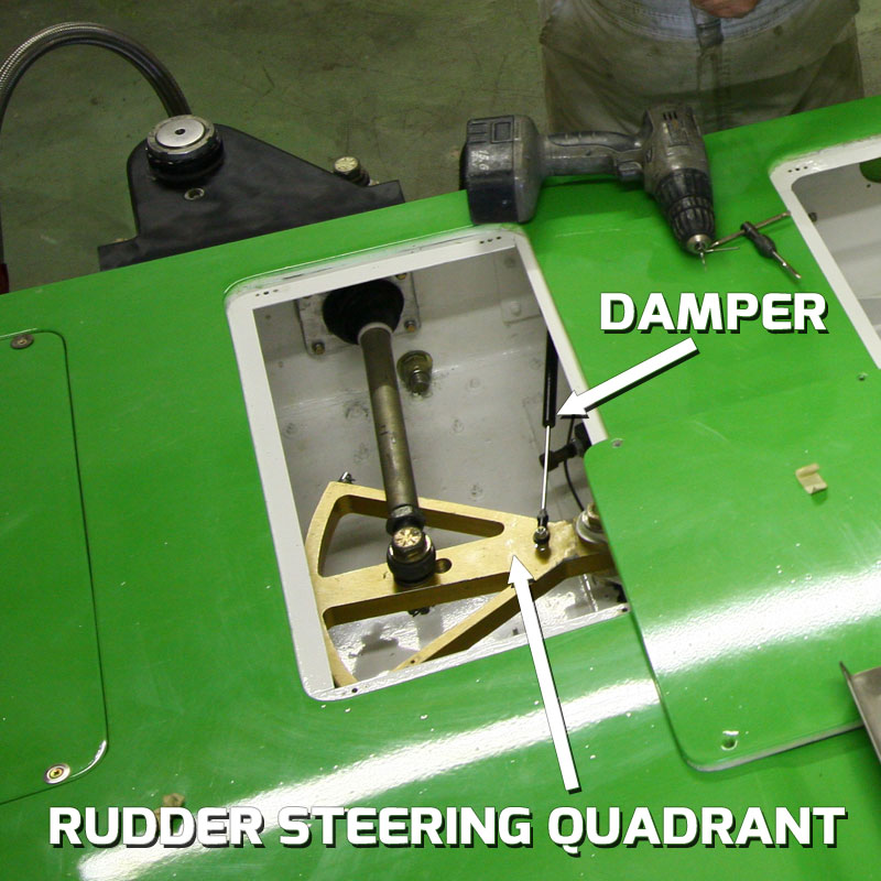
In the video below, you can see the result of losing the rudder at high speed. In Heat 1A at the 2014 Bill Muncey Cup in San Diego, as Jon Zimmerman was entering the first turn on the first lap, the rudder bracket broke, instantly snapping the boat sideways. Luckily, he did not cross into the path of another boat, but the damage ended the team’s weekend.

Whether you have been a fan for decades or are just learning about the sport of Unlimited Hydroplane racing, we want to help you learn about all facets of our sport – from a basic explanation of the races so you know what “heats” are and how to keep score, up to the intricacies of the Lycoming T-55 L7 gas turbine & Allison V-12 engines that power our boats and the aerodynamic forces that put the “plane” in “hydroplane”. It’s all here!
H1 UNLIMITED – THE SANCTIONING BODY
H1 Unlimited is the sanctioning body for the sport of Unlimited Hydroplane Racing in the Unites States. As a member of the APBA (American Powerboat Racing Association), we establish the rules that govern our races, the qualifications of the drivers, boats and the courses we run on. We also supply the personnel and equipment to put on the race at each venue, from the rescue crew to the media team to the tech personnel that insure everyone plays fair.
All of the members of the H1 Unlimited team are volunteers and all are long-term veterans of the sport, beginning as racers, crew, media or just plain fans. Most of our volunteers have been around boat racing for decades, involved at every level imaginable.
If you are at one of our races and want to learn more about the sport or volunteer your time, be sure to flag down a “Blue Shirt”!
The H1 Unlimited staff are volunteers that love the sport and it’s history and are working very hard to insure its future. From the Board of Directors to the Referees, Timing and Scoring, PA Announcers, Media and Technical staff, we all enjoy bringing the fastest boats on the water to your lakes, rivers and bays every year! Thanks for coming out to see races!
Meet the H1 Unlimited 2024 Staff:
H1 UNLIMITED BOARD OF DIRECTORS:
Mike Denslow – Chairman
Darrell Strong
Charlie Grooms
Shannon Raney
Kelly Stocklin
Brad Luce
REFEREES:
Jonathan Abbott – Head Referee
Matt Yarno – Assistant Referee
Sam Houghtaling – Assistant Referee
OPERATIONS:
Taryn Baze – Operations Director
Mark Mallory – Pit Boss
Jeff Shepherd – Assistant Pit Boss
Heidi Dunk-Vincent – Pit Operations
Don Agopsowicz – Truck Driver
Heidi Dunk-Vincent – Pit Operations
Suzy Shepherd – Risk Manager – Corral
Emily Raney – Credentials/Social Media
Ashley Raney – Credentials
RESCUE & MEDICAL:
Dave White – Director of Water Safety
Brannon Casler – Rescue
Dave Stering – Rescue
Joe Carrington – Rescue
Cathy Spry – Medical
TIMING & SCORING:
Jim Sharkey – Timer
Mary Compton – Timer
Nick Kish – Data
TECHNICAL:
Seph Parshall – Technical Referee
John Walters – Chief Inspector
Steve Compton – Tech Inspector
Brian Vincent – Tech Inspector
DRONES:
Lisa Courneya – Flight Director
Brian Montgomery – Drone Pilot
Dan Foard – Drone Pilot
MEDIA:
Tait Meyer – Live Stream
Jared Meyer – Live Stream
Matt Johnson – Live Stream
Chris Denslow – Photographer
Brad Luce – PA
Tana Morrisett – Media Liaison
Walt Ottenad – Website / Onboard Video / App
H1 Unlimited live-streams every session with boats on the water all season long on YouTube and Facebook.
Tait and Jared Meyer, brothers from Richland, WA established our current live streaming video program during the 2018 season and have refined it ever since, now bringing a full HD stream to any device that can receive it, anywhere in the world. With the addition of production assistant Matt Johnson in 2022, we feel the livestream is the equal of any out there and brings you right to the shore for every one of our events!
At each race site, the crew sets up all of our gear the day before racing begins and tests the equipment, the connectivity and the final output so we are ready to bring our races to the world once testing starts. Every streaming session includes multiple camera angles from our on-shore cameras, drone cameras and remote cameras.
All sessions can be viewed on our YouTube channel and our Facebook page, as well as the H1 website – just click the “Video” menu item to watch all of our videos! Our livestream from Seattle is a great example of what you can expect from our streaming team:
In order to officiate our races, referees need to have an unobstructed view of the race course and all the boats on it.
In the past, this was accomplished by having a helicopter parked over each turn, with assistant referees in each one, keeping an eye on lane violations, overlap and other potential driving infractions. While helicopters were great for actually putting our referees eyes on the course, they were loud and rough, which made communication by the referees hard to hear and because having video evidence to review is critical to making the correct calls, helicopters were not ideal because the video our referees shot was EXTREMELY jerky due to the main rotor’s vibrations, as you can see in the following clip:
Additionally, if the video needed to be reviewed, it was a very laborious process, as the helicopters needed to land and the camera transported to a monitor for review, then referee and camera had to be transported back to the helicopter for the next heat.
First discussed in 2014, H1 Unlimited began a feasibility study to determine if the helicopters could be replaced by drones, while still allowing referees to have the full picture of the racecourse as they would have from the helicopter.
Beginning in 2017, we started experimenting with drones that recorded video our referees could review after the heats were finished. The results were pretty extraordinary, but we could not rely on the video files to make decisions immediately, as the technology was not quite there to allow the real-time viewing that was required in order to shift completely away from the choppers.
In 2019, H1 Unlimited official Lisa Courneya established our Drone program that completely eliminated the use of helicopters by allowing our officials to see the view from each drone in real-time on monitors on the Judges Stand. Our drone team now includes Brian Montgomery, son of long-time H1 Unlimited announcer Steve Montgomery and long-time H1 contributor Dan Foard – the first person to fly an FAA-authorized drone over one of our events, in 2015. They bring a full complement of five DJI Mavic Pro 3 drones, along with hundreds of pounds of gear to each event to “fly” our referees to the prime viewing spots above each course.
The views from our drones are spectacular and allow a “camera on a pole” view from each turn on the racecourse, with an ultra-stable platform to view and record every heat. The video feed is sent from our pilot’s controllers directly to our video switcher, then to our Live Stream and the referee’s 35″ HDTV monitors equipped with DVR’s that allow them to immediately review their footage in order to make calls – most of the time before the boats even reach the dock!
Watch some of the drone footage in this Guntersville Final Heat review to get a feel for how much better the view is!
Society lives by rules and things are no different with H1 Unlimited. From what is allowed (and not allowed) on the boats to how the races are run and how the courses are set up, it’s all here.
THE RACES
Unlimited hydroplane racing has a long and colorful history, and the Hydroplane and Raceboat Museum is a great place to start learning more about the history of Unlimited hydroplane racing. The museum (also known as HARM) is located in Kent, WA and has an amazing collection of hydroplane memorabilia as well as many restored hydroplanes. Volunteers at the museum have restored some of Unlimited racing’s most beloved hulls: the 1955 Miss Thriftway , the 1957 Miss Wahoo, the 1962-65 Miss Bardahl, the 1973 Pay N’ Pak, the 1977 Atlas Van Lines “Blue Blaster” and the 1980 Miss Budweiser, among others.
At H1 Unlimited events in Tri-Cities, Seattle and others, exhibitions by some of the most famous hulls in Unlimited history are a part of the show. Learn more about the Museum’s mission by watching some of the videos below, and we wholeheartedly encourage you to visit the museum in person, and visit the websites we have included in the “Links” section below to learn more about the people, technology and the beautiful fast boats that make up the incredibly long and rich history of Unlimited hydroplane racing:
Boat racing in the Unites States has been going on since men first set sail, but organized powerboat racing began in the earliest parts of the 20th century and continues in a myriad of classes to the present day. The American Powerboat Association (APBA) is the sanctioning body for almost all forms of boat racing, but H1 Unlimited is the sanctioning body for all of our events except one.
Every year, Unlimited hydroplanes race for the oldest motorsports trophy in the United States: the APBA Gold Cup. The legacy of this trophy began in 1904, a full five years before what most consider to be the oldest motorsports trophy in the US: the Borg-Warner trophy given to the victor at the Indy 500. Except for a stretch during World War 2, the APBA Gold Cup has been awarded every year since 1904, and is the most prized trophy in Unlimited racing.
Unlimited hydroplanes have gone through five distinct periods of boat design and powerplant combinations: from the early part of the 20th century through the late 1940’s, conventional front engine, rear drive, deep “V” planing hulls that used a multitude of internal combustion engines were the standard and were not a huge break from then-current boat design norms. These designs stayed fairly static, with only incremental improvements.
In fact, the word “hydroplane” was not even associated with our class of boats until some pretty radical design changes were incorporated. In the early 1950’s, the second generation came in with a bang: the modern design standard of the round (or “shovel”) nose three-point hydroplane (a prop-riding boat with outboard sponsons that skipped on the water) began with what are widely regarded as the ancestors of modern racing hydroplanes: the Slo-Mo IV and Slo-Mo V, designed by Ted Jones of Seattle.
Almost all boats of the era were powered by then-plentiful WWII surplus aircraft engines and many colorful drivers were household names: Big-band leader Guy Lombardo, Chuck Thompson, “Wild” Bill Cantrell, Mira Slovak, Jack Regas and Bill Muncey among many others.
The U-1 Miss Bardahl – “The Checkerboard Comet” – was an example of state of the art hydroplane design in the late 1960’s. With Billy Schumacher driving, it won the championship in 1968. HARM photo:
In the design that dominated racing for almost twenty years, the driver sat behind the engine and the front of the boat had a rounded nose with the “sponsons” outboard of the center section, extending from the nose and ending about the back of the engine. The propeller on these boats was driven directly from the engine, so the engines were tilted at the same angle as the propeller shaft.
Unfortunately, these designs had disastrous consequences when the boats crashed, and many drivers were killed when the boats hit large swells, causing them to nose into the water at very high speeds. The worst day in the history of Unlimited racing occurred in 1966 at the Presidents Cup in Washington D.C. when three drivers: Don Wilson, Rex Manchester and Ron Musson were killed on the same day:
To try and combat these handling issues, some designers started experimenting with “cabover” designs, placing the driver ahead of the engine, changing the center of gravity to try and prevent these nose-first crashes. Even with more and more powerful engines, now capable of producing over 2,000 horsepower; the racing became marginally safer, but was still a very dangerous sport and drivers were still losing their lives.
Guaranteeing driver safety was a very slow process that had no clear-cut answer as the sport headed into the 1970’s. During the early 70’s, almost all consistent winners were still using aircraft power and the “conventional” round-nose hull.
The third generation of Unlimited hydroplane design came about with the popularity of the “pickle-fork”, or twin boom design familiar today that put the tips of the sponsons out in front of the center section.
Whether it was a conventional design or cabover, by the mid-70’s almost all winning Unlimiteds used this new design. Also, as surplus aircraft engines began getting more expensive in the early to mid1970’s, some teams began experimenting with now surplus turbine power plants that powered the Army’s helicopters.
The fourth generation of Unlimiteds began in 1973 when a group in Seattle launched the U-95, a twin turbine design that ultimately started a revolution that changed the sport. It utilized two turbine engines and was the modern cabover “pickle-fork” design.
As costs continued to climb for the V-12 engines, the turbines were now becoming more readily available and were reliably churning out more horsepower than the internal combustion engines and requiring far less maintenance over the course of a race season. The integration of turbines was a very slow process, taking many years to prove that they were a match for the aircraft engines, but as the sport moved into the next decade, the winning combination proved to be the turbine engined cabover design, and Unlimited racing in the 1980’s proved once and for all that the turbines were the way forward.
The U-95 was the predecessor to the turbine Unlimiteds you see today. HARM photo:
As the aerodynamic portion of race boat design was becoming better understood, Unlimiteds also began taking advantage of these aerodynamic principles: the overall shape of the boats allowed them to function almost like a wing, with the “tunnel” under the boat being fine-tuned to allow the boat to more effectively use the air itself to lift the boat. Sponson designs of the “pickle-fork” boats were increasingly helping the boats to skip on the water easier and turn better.
Various teams started experimenting with other aero devices like rear wings, trailing moveable flaps to control the air at the front of the boat, and finally the modern moveable canard wing you see on our modern hydroplanes.
Three dominant hydros of the 1970’s and 80’s: the 1973 Pay ‘n Pak, 1977 Atlas Van Lines “Blue Blaster” and the 1980 Miss Budweiser:

During every race, the driver and boat collect points for their qualifying performance and heat finishes. The boats that have accumulated the most points during the preliminary heats make it to the winner-take-all Final Heat. Note that we said “boats” – if multiple drivers drive the same boat and score points during an event, it’s the boat, not the driver that qualifies for the Final Heat. There is no guarantee that the boat that wins the Final Heat will come away with the most points.
Points are awarded for every session that features competition, such as qualifying, preliminary heats and the final heat. Points are not awarded for testing or exhibition runs.
For qualifying, the points break down like this:
- 1st Place qualifier receives 100 points
- 2nd Place: 80 points
- 3rd Place: 70 points
- 4th Place: 60 points
- 5th Place: 50 points
- 6th Place: 40 points
- Remaining boats that qualify above 130 MPH receive 30 points each.
- Boats that do not qualify or reach the 130 MPH threshold are awarded no points.
After each preliminary heat and the final heat, boats are awarded points based on how they finished. Each finishing place receives 75% of the points of the previous finisher :
- 1st Place: 400 points
- 2nd Place: 300 points
- 3rd Place: 225 points
- 4th Place: 169 points
- 5th Place: 127 points
- 6th Place: 95 points
- 7th Place: 71 points.
Points can be deducted for various rule infractions such as N2 or fuel violations, lane violations or unsportsmanlike conduct.
The winner of each race is determined by their finish in the Final Heat – points accumulated throughout the weekend have no bearing on their placing in the race – they only count toward the end of the season championship standings.
Points will count towards the National Champion Trophy for drivers and the National Champion “Martini & Rossi Trophy” for owners. Here again, there is no guarantee that the boat that wins the most races during the season will win the Championship.
For instance, the 2014 season saw J. Michael Kelly in the U-1 Graham Trucking win four of the six races, but Jimmy Shane in the U-6 Oberto took the Championship at the second to last heat of the season by virtue of accumulating more points.
Contrary to most other forms of motorsport that race on tracks with lanes or a starting grid where the cars will form up prior to the start and in their assigned starting positions, our drivers are free to try and grab any starting position they choose prior to the start, and that process starts with and is driven by a clock.
Each driver and crew chief will have their own clocks that they will synchronize EXACTLY to the official countdown clock so they can be as accurate as possible in timing their run up to the starting line, as the drivers will try to pass the start/finish line at EXACTLY 0:00 at full throttle – usually at around160MPH! Too soon, and they will have “jumped the gun” and will be issued a time or lap penalty, essentially ending their race. Considering that if the boat was traveling at 160MPH, it is covering 234 feet per second, so it shows just how critical that synchronization process is!
Prior to the start of each preliminary heat and winner-take all final, the official clock will count backwards starting at “10 to the 5” – this means that it is “ten minutes to the five minute gun”, or fifteen minutes to the start of the heat. This will be announced over the PA system but this callout is not super critical for the racers – this is when most boats will be lowered by crane into the water and drivers will be getting ready to enter the cockpit.
At “5 to the 5” (five minutes to the five minute gun), there will be another callout on the PA and usually in the driver’s earpieces from their radio man – and it is critical for them at this point to insure they are synchronized to the official clock. All drivers will be strapped into the boats with their safety gear in place and most will continue to check for exact synchronization with the official clock as each minute passes.
As the clock winds down to five minutes, there will be a ten-second count over the PA system. At five minutes, most drivers will fire their engines, leave the dock and enter the race course. The only exception to this is in Guntersville, where due to the length the boats must travel to enter the racecourse, they leave at six minutes.
At the one minute mark, or one minute “gun”, all boats must be up and running or they will be held at the dock and not allowed to take part in the race.
The 5 minute interval between the boats leaving the dock and arriving at the start is called the “milling period”, where each driver can go almost wherever they want on the race course to place themselves where they think they have the best shot at winning. What may look like a bunch of boats going slowly in circles is actually a VERY well thought-out process, and usually the subject of much planning prior to each heat.
Based on timing runs that each driver would have done in practice, he will know how long it takes him to pass the buoys on the course at a steady speed, so he will have a good idea of where he needs to be on the course and at what speed to allow him to make it to the start on time. However, these plans can definitely be thrown out the window based on lane position, positions of the other boats or other unforeseen circumstances that happen in the milling period.
You will likely see boats “cut the course” – moving from front stretch to back stretch and vice-versa through the infield at designated areas. This occurs when the driver is either out of place from where they need to be at a particular time, or it can be used to block another boat from grabbing an inside lane. However, there are areas inside the course where the rescue and judge boats are located, called the “DMZ” areas, and are clearly marked with buoys so the driver knows not to enter. If a driver does enter a DMZ, it is an immediate disqualification.
In the period before the start, all boats must maintain a minimum speed of 80 MPH as well, which is monitored via GPS on the onboard data logger and reviewed after each heat of racing. If it is discovered that the driver went below 80MPH for more than 5 seconds, they are disqualified. Look for the roostertail to be above the rear wing – if it drops below for any length of time, it’s a good indication the boat is going too slow and the driver may be in danger of that DSQ after his data is read.
Since the shortest way around the course is on the inside, Lane 1 is generally the preferred lane to start in, but the driver may definitely not want Lane 1 due to the way the boat is set up. If they have added taller gears in the gearbox or changed the propeller to maximize speed instead of acceleration, Lane 2 may be more to their advantage. Very rarely would any driver want to start from outside Lane 2. Since all boats were allowed to “fight for lanes” prior to the start, the driver that was the best at pre-race strategy usually ends up where they want to be and the rest of the field may have to run their race in a compromised lane choice.
Once lanes are established at the entrance to the turn prior to the start, all of the drivers will position themselves so that they reach the start/finish line as the official clock strikes 0:00, signifying the start of the race. Drivers do not want to “beat the clock” or they will be assessed a penalty, usually in the form of an additional lap or additional time added to their finishing time.
Keep an eye on any boats that are late to the start, ESPECIALLY if they have boats ahead of them on either side, as the run down to turn one can end up with the slower driver entering a “tunnel” formed by the roostertails of the faster boats, which is VERY powerful and can easily flip the boat or shred the canard, cowling and rear wing.
To sum up: if the driver and crew chief have done their pre-race planning, set up their boat correctly with the right gears and prop, synchronized their clocks, adhered to their timing marks, avoided other boats and grabbed their preferred lane, they MAY come away with a victory. If anything was overlooked or mistakes were made during the milling period, there are 4 or 5 other drivers that probably got it right and can take the win instead…
SAFETY SYSTEMS
By Dixon Smith
Question 1: Can a raceboat be made that will not flip?
Answer: Probably.
Question 2: Can that unflippable boat be a consistent winner?
Answer: Yes, but as one pundit said many years ago about another program, “when the Boeing Board of Directors changes the basic laws of Physics or gives us an endless budget, we can make this work.”
Real Answer: NO, not with current technology.
First a little history. Current race boats as we know them are generally called 3 point hydroplanes or prop-riders. This is because they ride on a small area at the back of each sponson and on the lower half of the propeller. The most famous first 3 pointer is the Slo Mo Shun IV. The Slo Mo IV was not the first 3 pointer, although it is the best known. There were a number of limited hydroplanes that were prop-riders prior to the Slo-Mo IV being built.
The first famous flip of a race boat occurred on Lake Washington in 1955 with the sister ship of the Slo-Mo IV, the Slo-Mo V, with Lou Fageol driving. The boat did a complete 360-degree flip and landed right side up, but with substantial damage. That happened over 50 years ago, and race boats are still flipping.
There have been several rather spectacular and famous flips in the unlimited class. In Pasco many years ago, the Pay ‘n Pak did a 720-degree flip, where it went around 2 times before hitting the water.
In San Diego in 1988, 2 boats, Circus Circus and the Miss Madison, did a side by side flip. A few years ago the Pico American Dream flipped in Seattle during a preliminary race heat, brought back to the pits upside down, repaired by the crew and ultimately won the final heat and the race.
There have been occasions where a unlimited race boat has done a 360-degree flip, landed right side up and continued running. When Steve David flipped the U-1 Oh Boy! Oberto in 2009 in Doha, the crew repaired the boat in time for the Final Heat, allowing Steve to take the 2009 High Points Championship!
Flips can injure the driver, but since the advent of the survival cell, very few drivers have been seriously injured and there have been no fatalities since the early 2000’s, when George Stratton was fatally inured in San Diego – mainly due to the lack of the HANS device (now mandatory for every driver).
Nearly all flips are disastrous to the boat – the least a hull can usually get away with is severe damage to the rear of the boat, and most boats that flip are very heavily damaged, requiring many hundreds of man-hours worth of repair before they can race again.
Corey Peabody flipped the U-9 Lynx Healthcare in Madison in 2022, just a week after winning the Gold Cup – doing extensive damage to the boat and taking it out of any further running in the 2022 season. The flip was so violent it ripped the entire right sponson off the boat!
Now, back to the questions.
First we need to understand a little about the physics of the problem. I will stay away from any equations, math or aerodynamic engineering stuff. I need to define a few things that will make this easier to understand.
Center of Gravity: The balance point of the boat. If you were to pick the boat up at only one point, and this was at the center of gravity, the boat would hang perfectly level. Without external forces, the boat will rotate around the center of gravity.
Center of Aerodynamic Lift: Some times called the center of pressure. If all of the aerodynamic lift were applied at the Center of Aerodynamic Lift, the effect on the boat would be the same as the real lift that the boat experiences.
Center of Hydrodynamic Lift: Same idea as the Center of Aerodynamic Lift, except the lift is from water, not air. These two are not in the same place.
Drag: All the stuff that keeps us from going fast. There is aerodynamic drag, drag from the air and hydrodynamic drag, drag from the water.
An interesting and important point is that water is about 800 times denser than air, or another way to say that is a bucket of water weighs about 800 times more than a bucket of air. If you don’t think air weighs anything or drag from air is not significant, hold your hand out the window of a car going 70 mph palm down, and then rotate your hand about 90 degrees and see what happens. Now think about that force, but multiplied 800 times, and you get an idea of the drag force from water.
Lift: To demonstrate aerodynamic lift, do the same experiment as above, hand out the window with palm down. Now rotate your hand a small amount in each direction and feel the upward or downward force. This is the lift force from the air. The same ratio of hydrodynamic drag to aerodynamic drag applies to lift. For a given speed and area, the lift from water is about 800 times the lift from air. That is why the sponson area in the water is very small compared to the total area of the boat.
Now, we need to have some stuff in the water, prop, rudder and skid fin. Anything else in the water is excess drag, and slows us down. So that is why to go fast, the boat needs to have as little sponson in the water as possible. The catch is how do we get as little sponson in the water as possible. Here is where those pesky laws of physics get in the way.
An arrow is a good example of something that works well aerodynamically. It has been developed over many thousands of years and has remained about the same for a long time, because it works. If you were to balance an arrow on your finger, you would find that the center of gravity is about 1/3 the distance back from the front. This is because the point on an arrow is somewhat heavy. The point being heavy is not only because it needs to be sharp and strong to penetrate a target or animal, but the weight up front makes the arrow more stable in flight.
Also, note the feathers are at the very back of the arrow. Remember the center of gravity is near the front, but the aerodynamic center is just in front of the feathers, very far back. Also, remember, per the definition of center of gravity, that the arrow, if disturbed in flight, will rotate about the center of gravity.
So if the arrow gets disturbed in flight and the front pitches up, it will rotate about the center of gravity, the tail will rotate down. When the tail rotates down, the feathers will increase lift and push the back up to re-level the arrow. If the nose of the arrow pitches down, the tail will rotate up, again around the center of gravity, and the feathers will push the tail down, again re-leveling the arrow. This is why an arrow flies straight and level. Arrows do not do 360-degree flips.
Well that sounds easy, let’s just design a boat like an arrow and make it stable. Here is where those pesky laws of physics and the practical world of boat racing don’t get along.
All raceboats have to be propelled by a water propeller. So, we need to keep the prop in the water. To do this, we need some significant weight on the prop. Most boats have about 1/3 of their weight on the prop and about 2/3 of their weight on the sponsons. To do this, means the center of gravity needs to be significantly behind the sponsons.
Remember that water drag is lots more than air drag, so we want to keep as much of the sponson out of the water as possible. The way this is done is to have the center of aerodynamic lift somewhat forward, to carry the sponsons, but not lift the prop out of the water. The result is the center of aerodynamic lift is forward of the center of gravity.
Two more pesky little problems rear their ugly heads about this time. The first is that lift goes up with speed, but much faster than speed. In fact, lift goes up with the square of speed. In other words, if speed increases 10% then lift increases 21%.
The other little problem is the center of lift is not in a fixed position, it moves around. The boat attitude, nose up or level, and height above the water both affect the position of the center of lift.
Here is the really bad news. As the boat pitches up, the overall lift on the boat increases. Remember the hand out the car window example and rotating your hand a small amount. Also, as the boat pitches up, the center of lift moves forward. Keep this in mind. Now, you say, but a lot of the boats now have canards that the driver can control.
For those who don’t know about canards, it is a movable wing, forward of the cockpit that the driver controls, typically with his left foot. With the canard, the driver has significant control of the overall aerodynamic lift on the boat.
Let’s put this all together and put the driver in the loop during a race. Remember, less sponson in the water makes us go faster. Also, both aerodynamic and hydrodynamic lift go up with speed, but faster than speed.
One last thing, the aerodynamic center of pressure moves forward when the boat pitches up. Race water, a bit rough, accelerating down the straight, need to go faster so use the canard to lift the sponsons to get them just touching the water. Speed is increasing, all is good. Turn coming up, look for the other boats, and the sponsons hit a wave that the driver didn’t see.
Because hydrodynamic lift is so strong and increases faster than boat speed, the boat pitches nose up. Two critical things happen when the boat pitches nose up: (1) the total lift on the boat increases very fast with pitch up, and (2) the center of lift moves forward.
If the driver is a little late changing the canard position, or the pitch up is so much that the canard cannot overcome the increased lift and center of pressure moving forward, then up we go. Initially the boat rotates around the prop, but as soon as the prop is out of the water, now the boat rotates around the center of gravity. This is why it looks like the boat hangs with the nose up for a short period of time, then quickly does some type of loop or roll.
Other things that can set the boat off and start the process of a flip are wind gusts and the boat entering a turn. The aerodynamic lift is a function of air speed, which is boat speed plus or minus wind. So on a gusty wind day, a gust of wind could increase the lift unexpectedly. This is a typical situation in San Diego, because of the local topography. Depending on boat design, entering a turn can significantly change the aerodynamic characteristics of a boat. Not all, but a significant percentage of flips occur at the entrance to a turn.
Back to the question of can a boat be designed to not flip and also be a winner? With the right stability control system, similar to what some fighter aircraft use, yes. For some classes of raceboats, these types of control systems are illegal at this time. Also, it will be very expensive to develop this type of system for a raceboat, well beyond the budget capabilities of most teams.
In conclusion, a good boat design and an experienced driver are the best insurance against flipping a boat. But, so far, nobody has built a boat that will not flip.
© Dixon Smith Dixon Smith was a long-time crew member on the Miss Budweiser hydroplane team. He began his racing career in the ‘60s on the crew of the Hawaii Kai III and Seattle Too. He refurbished the 1962-65 Miss Bardhal and drives it at vintage hydroplane exhibitions in Kennewick, Seattle and Chelan, WA.
By Roger Schaffer
The following essay was written in the 1990’s, but most of the principles outlined here are the same for current Unlimited designs.
A blowover is probably the most spectacular accident in motor racing. They have haunted our sport since the Slo-mo V flipped qualifying for the 1955 Gold Cup in Seattle. I witnessed this accident and have been interested in their cause ever since. Even though serious injuries and fatalities have been prevented by the enclosed cockpit, the high incidence of these accidents is a real cause for concern. By my count there have been at least 32 blowovers since the Slo-mo V flip. This last year alone there were six flips. The incidence of accidents has increased even though the boats have become much more technically sophisticated and many designs have been wind tunnel tested. What is going on here and how can the frequency of these accidents be reduced? This article examines the underlying cause of blowovers and makes some suggestions on how they can be reduced. Please don’t be put off by the technical terms. After this article you’ll be able to snow just about any hydro fan.
Lets face it, a hydroplane is basically a very low flying airplane. It makes sense that the same principles that apply to airplane stability can be used to understand blowovers. First, when is a hydro an airplane? Clearly when the aerodynamic lift is more than the weight of the boat, its an airplane (the rudder, skid fin and prop might still be in the water, but for all intents and purposes the hydroplane has become an airplane). Airplanes always take off when going into the wind and hydroplanes almost always blowover when going into the wind. This is because aerodynamic lift is due to the square of the relative wind speed over the wing. If the boat is doing 180 mph and hits a 20 mph wind gust it suddenly sees a 200 mph relative wind and the aerodynamic lift increases by 24 percent ((200/180)**2=1.24). In fact the speed at which a hydroplane becomes an airplane can be pretty accurately estimated by the formula: V = 45 x (W/S)**.5
In this formula V is the relative wind speed in miles per hour when the hydro is completely airborne. The term W/S is the wing loading and is simply the total weight of the boat divided by its deck area. The wing loading for current hydros is around 17 to 22 pounds per square foot. The square root of these values is between 4.1 and 4.7. This puts the blowover velocity at 185 to 210 miles per hour less any wind gusts. This formula tells us what we already know: light boats with lots of wing area fly (and will blowover if not stable) at lower speeds then heavier boats.
To keep from blowing over when in the airplane mode the hydro must have positive stability. This means that if the bow pitches up, even a little, there must be a “moment” produced by the boat that tends to pitch the bow back down. (A “moment” is simply a force that acts through a distance. A more common term for moment is “torque” and either term can be used. A wrench produces a moment or torque by applying a force multiplied by the length of the wrench.) If the moment produced by the boat is not strong enough, then the bow will continue to rotate up and over. What causes the stabilizing and the restoring moments? That is the essence of stability, but first some terms must be defined.
For safety, every airplane has a forward and aft limit on its center of gravity location. This location is established by the manufacturer and is based on the design of the airplane and FAA regulations. The “center of gravity” is the point where all the weight can be considered to be concentrated; it is the point where an object would balance if hung from a single cable. If a hydro is horizontal when lifted off its trailer, its center of gravity will be exactly between the forward and aft lifting points. If the boat points bow up when lifted, its center of gravity is aft of this mid- point. The aft most location of the center of gravity where an airplane is stable is called the “neutral point”.
For our purposes, the neutral point is the same as what engineers call the “aerodynamic center”. The aerodynamic center is the point where the aerodynamic lift can be considered to be concentrated and where the aerodynamic moment is constant. Sometimes you will here the term “center of pressure” used. It should not be confused with the “aerodynamic center”. The center of pressure is where all the aerodynamic lift can be considered to be concentrated and where there is no net aerodynamic moment. The problem is: the center of pressure moves allover the place depending on the angle of attack and height of the hydroplane. The neutral point does not move with angle of attack. Unfortunately, for most hydroplane configurations, it also changes with height above the water. Nevertheless, the neutral point is a better concept to deal with.
It is relatively straight forward for an aerodynamicist to determine the location of the neutral point for an airplane. This can be done using mathematical equations or by wind tunnel testing. However, it is very difficult to establish the neutral point for a hydroplane because of the effect of flying very close to the water. This so called “ground effect” greatly changes the way the air flows around a shape. It makes it hard to estimate the neutral point either analytically or by wind tunnel tests. To understand why ground effect causes this difficulty it is necessary to understand how the air flows around a hydroplane.
Air that hits a hydro between the sponsons either goes over or under the boat. The air that goes over the top will create a suction pressure due to the curvature of the shape, just like the upper surface of an airplane wing. This low pressure tends to be concentrated at about 25 percent of the length of the wing aft of the leading edge, just like an airplane. The air that goes under the boat behaves much different than an airplane due to the presence of the water surface. The bottom of a hydroplane is basically flat and slopes down from bow to stern.
You can better visualize the bottom shape of the boat by looking at the trailer when the boat has been removed. This bottom angle plus the sponsons and “air traps” along the sides form a scoop. This scoop stops or “stagnates” the air and generates the same type of pressure you feel if you cup your hand and hold it outside a car window. This pressure is pretty much the same all over the sloping part of the bottom of the boat. Therefore, the lift force from the underside of the boat is concentrated close to 50 percent of the distance back from the leading edge of the wing to where the slope ends.
The stability problem is largely due to the fact that the upper and lower surface lift forces act at different locations. The stability problem normally begins when the aerodynamic lift on the boat exceeds the weight of the boat. As shown above, this can easily happen when a head wind or gust is encountered. When the aerodynamic lift is greater than the weight there is a net upward force on the boat and the boat tends to move away from the surface of the water. Even a small upward movement allows more air to escape from the transom and sides of the bottom surface. This increased area for the air to escape is like a leak that allows the air bubble of stagnant air that the boat has been riding to escape more easily. The air pressure under the boat decreases while the air pressure on the upper surface does not change.
So a boat that was in perfect balance just an instant before hitting the gust now has a net bow up moment acting on it. This new torque is due to the change in lift on the under side of the boat and the fact that the upper and lower surface lift forces act at different locations. This new torque tends to rotate the bow up. If there is no other lifting surface (like a horizontal stabilizer) to produce a torque to counter balance the bow up torque, the boat will continue to rotate producing the classic blowover.
This explanation leads to the conclusion that boats without horizontal stabilizers will tend to blowover when ever the aerodynamic lift exceeds their weight. (The rudder and skid fin produce a moment which tends to keep the bow down, but only to a point.) Adding a horizontal stabilizer helps, but will not prevent a blowover. The restoring torque that the horizontal stabilizer produces is due to its surface area, distance from the center of gravity of the boat, and rate of change of its lift with angle of attack. If the center of gravity is aft of the neutral point the restoring torque will be insufficient to counter balance the destabilizing torque produced by the change in lower surface pressure. Even with a horizontal stabilizer, there will always be a center of gravity location where the boat will be unstable. Changing the angle of attack of the horizontal stabilizer does not move the neutral point; it only changes the amount of lift that it produces which changes the attitude of the boat which indirectly changes the blowover speed.
Most boats now have small wings that connect the sponsons and the fuselage. These “canards” have flaps along their trailing edge that the driver can control. These canards can change the attitude of the boat and can improve the stability of the boat if operated precisely by the driver. However, this is very difficult and because they produce a lifting force forward of the center of gravity they actually move the neutral point forward, closer to the center of gravity, which is destabilizing.
Several boats including this years T Plus have tried the two-wing (tandem wing) design. The advantage of this configuration is that the neutral point does not move forward when the height of the boat above the water increases; the neutral point remains fixed like on a conventional airplane flying out of ground effect. This makes it easier to estimate the location of the neutral point. However, it does not mean that two-wing boats can not blowover – they still can if the center of gravity is aft of the neutral point and the boat exceeds the blowover speed.
There are other mechanisms that can cause blowovers. The most common are the sudden lost of the rudder, skid fin or propeller blade. For example, the Miss KISW flipped in a practice run in Seattle this summer when its rudder came off. The rudder and skid fin produce a large amount of drag. Because this drag is below the center of gravity they tend to hold the bow of the boat down. When the rudder or skid fin suddenly come off this restoring moment is lost and the boat is left with a net aerodynamic moment that tends to pitch the bow up. Again, unless the center of gravity is far enough forward and the horizontal stabilizer is big enough, the boat will continue to rotate up and over.
Until recently the loss of a propeller blade would often cause a blowover. The propeller produces a considerable amount of lift this is what holds the back end of the boat out of the water. Because this lift is well aft of the center of gravity the propeller lift tends to hold the bow down. The loss of a propeller blade, just like the loss of a skid fin or rudder, leaves the boat with a net bow up torque. If the boat is at or above its blowover speed it will flip unless there is sufficient restoring moment. Horizontal stabilizers and the “shoes” on the transom of most boats are helpful in producing this restoring moment and the loss of a propeller blade is much less of a problem then it once was.
Another situation that can cause a blowover is inadvertent movement of the center of gravity. If a boat gets a significant amount of water in its bilges and the water moves to the aft end of the boat, the center of gravity can move far enough to make the boat unstable. This was the cause of the flip of the 7 litre hydro Record 7 that almost killed Tommy Fults during a straight away record attempt in 1969. Boats should be designed to prevent the accumulation and movement of water inside the boat. Likewise, the fuel tanks should be at or aft of the center of gravity to prevent the center of gravity from moving aft when the fuel is burned off.
Is it possible to prevent blowovers? Probably not. However, it should be possible to reduce their frequency. The best solution would appear to be high quality wind tunnel testing to determine the location of the neutral point and its movement with height. Constant monitoring of the center of gravity to keep it forward of the neutral point by a safe margin would then be necessary. Wind tunnel testing is expensive and simulation of the ground effect is difficult. However, the cost of a blowover is also expensive, both in terms of damaged equipment and injuries to the driver.
Another option is to develop a design that automatically “bleeds off” excess air pressure to hold the aerodynamic lift to a value slightly less than the weight of the boat. If this could be done the hydroplane would never become an airplane.
Blowovers will likely remain a threat in hydroplane racing. However, they do not have to be a certainty, depending only on the next gust of wind. I hope this article helps in the understanding of these spectacular accidents.
In the previous section, you’ve seen what can happen when the boats flip, and that’s only one of the potential dangers to our boats and drivers.
A single blade inside a turbine engine can fail, leaving $100,000 worth of scrap metal in it’s wake. Gearboxes can fail, turning $50,000 worth of precision machined parts into a pile of junk. A tiny crack on a propeller can suddenly cause a blade to break at 9,000 RPM, ripping the back half of the boat apart, potentially sending it to the bottom.
Unlimited hydroplanes are some of the most spectacular racing vehicles on the planet and put on an amazing show any time they are on the water. Unfortunately, in any machine traveling 200+ MPH on the water, there are a LOT of things that can go wrong.
COLLISIONS:
At the 2017 Gold Cup in Detroit, Bert Henderson spun in front of J. Michael Kelly’s U-12 Graham Trucking hydro, leaving Kelly nowhere to go but over the top of Henderson’s U-7 Spirit of Detroit. Fortunately, neither driver was injured in the accident.
At the 2013 UIM World Championship in Doha, Qatar, Tom Thompson’s U-11 Peters & May ran wide into Brian Perkins’ U-21 Snoqualmie Casino and ended up being catapulted up and over the top, into Doha Bay sideways at 130+ MPH. The impact completely destroyed the U-11 and severely damaged the U-21.
In one of the most dramatic examples of things going wrong in recent memory, the video below shows the final heat at the 2011 Madison Regatta from onboard the U-1 Oh Boy! Oberto. In the final, Dave Villwock in the U-96 Spirit of Qatar was leading Steve David in the U-1 Oh Boy! Oberto into turn 1 on lap 4 when Villwock hit a “hole” in the water, snapping the boat sideways directly into the path of David, and at over 100 MPH, there was no time to react.
Due to the tremendous strength of the structure in both boats and the safety features built in, Steve David suffered only some cracked ribs and Dave Villwock was unhurt in the accident. The U-96 raced the following weekend in Detroit, the U-1 was on the water later in the season.
Cockpit design has evolved over dozens of years of racing and has progressed to the current design, which is a more or less standardized “survival cell” for the driver.
The cell is framed in tubular steel and wrapped in composite and carbon fiber to make it as strong as possible, with a similarly constructed lid on top and an escape hatch with a Lexan window in the floor. There is a steel spar that spans between the sponsons and attaches to the front of the cockpit, forming an incredibly rigid structure that can withstand almost any impact.
The windshield is from an F-16 fighter jet and side windows are usually made of bulletproof Lexan. 
Almost all modern hydroplanes use the newest cockpit design that incorporates a roof hatch that opens forward, but some older boats still use a hatch that hinges open to the side. These are being phased out due to the additional safety margin of the newer designs.
In the video below, in Heat 2A of the UIM World Championship in Doha, Qatar, Brian Perkins’ U-21 Snoqualmie Casino was run over by the U-11 Miss Peters & May of Tom Thompson. This dramatic video shows how the survival cell kept Perkins safe, allowing the U-11 to roll over the top of the boat rather than entering the cockpit. Perkins was uninjured in the incident and Thompson suffered a relatively minor arm injury.
Normal access to the cockpit is through the top hatch, but if a hydroplane flips and lands upside-down, the driver needs a way to get out. Since the roof hatch is now under water, it cannot be opened, so the only practical way for the driver to get out of the cockpit is through the escape hatch built into the floor.
All hydroplanes have this mandatory escape hatch, and it can be opened either by the driver from inside the cockpit or by rescue personnel from outside if the driver is incapacitated. The hatch covers and latches are standardized so all drivers and rescue personnel don’t have to memorize any boat’s particular arrangement in an emergency, which can cost valuable time in a recovery.

All current hydroplanes have escape hatches with a Lexan window that allows rescue personnel to see inside the cockpit prior to opening the hatch. Although flips are fairly infrequent, the hatches have been used a few times in the past decade and in every case, they performed as intended, allowing the driver to exit the (now underwater) cockpit quickly.
In the clip below, you see J. Michael Kelly flip the U-7 at the Columbia Cup in 2007, and very shortly after the boat has settled in the water, he opened the escape hatch and climbed out.
The driver wears a standard open-faced, rather than a closed-face helmet. This arrangement allows him to wear the air mask that provides an air supply and radio microphone, as well as attachment points for the required HANS device. Some drivers may also mount a visor or a fighter pilot style glare shield that flips down in front of their eyes instead of sunglasses to cut down on the considerable glare experienced at some race sites, particularly in the latter part of the day as the sun lowers on the horizon.

The air mask is the single most important piece of safety gear the driver has. In the event of a flip, the cockpit may fill with water and the air mask functions the same as a scuba diver’s regulator, providing air to the driver from an onboard scuba tank located behind the cockpit. This air supply is good for at least 15 minutes.
The mask also contains the microphone for the boat’s radio system, allowing the driver to communicate with his radio man. The microphone “talk” switch is normally a button located on the steering wheel and the radio speakers are contained in custom-fit earplugs that the driver may tape in place to keep them from being jarred loose. Both the air and radio systems have connectors that allow the mask to be connected and disconnected quickly.
Here Jimmy Shane tests the air mask for proper operation prior to testing – also note the earplugs:

Just like NASCAR, Indy Car and other top tier motorsports, our drivers wear a HANS device while driving their Unlimited hydroplanes.
HANS stands for Head And Neck Support and was developed to greatly reduce the possibility of head and neck injury to the driver by helping to immobilize the head during violent crashes. The HANS device operates by fitting a support made from carbon fiber shaped in a “U” across the driver’s shoulders with the portion behind the driver’s head raised in order to hold tethers that attach to the helmet.
Once the driver is strapped in, the HANS device is held under the seatbelts, forming a solid anchor for the tethers.

1. HANS device, 2. Tether (one per side), 3. Helmet anchor (one per side), and 4. Shoulder support.
During a crash, the tethers limit the range of motion of the driver’s head, helping to eliminate the possibility of head and neck injury. Almost all boats also include a padded structure (head rest) on the right side of the seat that limits the motion of the driver’s head during hard cornering. Considering that our boats corner with 5+ G forces, this helps the driver keep his head upright.

The driving suit worn by H1 Unlimited drivers is of the same type you would see in any top tier motorsport – H1 rules require that the driver’s suit be fire retardant with tight fitting cuffs. Gloves and racing shoes complete the suit. A flotation vest or life jacket is also required, and this may be either under or over the driving suit.

THE DRIVER
To drive a modern Unlimited Hydroplane competitively requires years of experience, usually gained in lower classes of inboard or outboard racing, with many drivers having started racing at the minimum APBA-sanctioned age of 9 years old. Experience alone does not guarantee a driver will end up in one of these boats, but it almost always will determine whether or not they will be successful.
In order to even qualify to drive an Unlimited hydroplane, a driver must be a certified SCUBA diver, pass a capsule training program, pass a physical examination, pass a test on the rules and then prove they are capable of producing the requisite speed – a driver must run a minimum of 15 timed laps (during one season) under the observation of the Chief Referee, 2/3 of which need to be above 130 MPH in order to start in a race.
Once the driver qualifies, they must start five seconds behind the front row for their first two heats of racing, and even then can still be assigned an outside starting position if the Chief Referee deems them needing more experience.
Only when the Chief Referee “signs off” on a driver are they fully qualified to compete from any starting position In contrast to Unlimited racing 40-50 years ago, drivers enjoy longer careers mainly due to the advancements in all aspects of the safety systems built into in our boats. Today’s drivers are also younger on average than in years past, with most of our current drivers under 40 years of age.
For almost all of our drivers, H1 Unlimited is a small part of their annual racing schedule, and when not racing Unlimited hydroplanes they can usually be found racing other classes of boats at local events around their hometowns and in national events.
The video below shows J. Michael Kelly in the cockpit of the U-5 Graham Trucking during the Final Heat at the 2015 Gold Cup, showing how brutal a ride in a modern Unlimited hydroplane can be, regularly subjecting the driver to lateral loads over 5 G’s and instantaneous vertical loads approaching 10 G’s.
https://www.youtube.com/watch?v=QdoKXs5DsboThe cockpit of a modern unlimited hydroplane is a very cramped space. There is not much room for anything that is not necessary to run the boat. In fact, just to allow the driver to get in and out of the cockpit, the steering wheel must be removed.

To enter the cockpit, the lid on the top of the cockpit is hinged at the front and flips up to allow the driver to enter. There is a release lever that allows the driver to open the lid from the inside and this is duplicated outside the cockpit as well.
Once the driver is situated in his form fitted seat, he gets strapped in with a five-point harness system that has a single release to quickly unbuckle all of the belts at once in case of an emergency. The driver cannot tighten these belts himself – this must be done by crew members who are helping him get ready. The rule of thumb is that when you get them tight enough that you can’t breathe, tighten them some more…
On either side of his head are padded supports for his head that limits the amount his head can move during 5+ G turns. In conjunction with the mandatory HANS device, the driver is using the latest in safety technology.
His feet rest on three pedals: the one on the right is the gas pedal, just as you would find in your own vehicle, but the two left pedals operate the front canard system, allowing the driver to control the attitude of the front of the boat with his left foot – push down on one pedal to lower the rear edge of the canard and raise the nose of the boat, or push down the other pedal to raise the rear of the canard, pushing the front of the boat down into the water.
Under the driver’s legs is the escape hatch that is his only way out if the hydroplane ends up upside down. All drivers must pass a capsule training test in order to race an unlimited hydroplane.
On the dashboard is usually a display panel or gauges that give the driver information on the engine such as N2 RPM, exhaust gas temperature (EGT) or other parameters. Usually there are one or two lights on the dashboard as well – these warn the driver when they are approaching the upper N2 RPM limit.
There are switches that control the flow of electricity to various items: a master on/off switch, emergency beacon, fuel pump, igniters, 24 and 48 V power for starting, and switches for the onboard Halon fire extinguisher system.
There are also levers that control the flow of fuel to the engine and since the engine will continue to run as long as it receives fuel, the adjustment on these levers is critical – this is the only way to turn off the engine once it has been started, so they have to be calibrated correctly.
The master switch for the electrical system and the fuel shutoff controls are duplicated on the outside of the cockpit as well so that rescue team members or crew can shut off all the systems on the hydroplane.
In the following infographic (courtesy of Ray Dong), you can follow the steps the driver and crew go through to get the driver ready and the boat started – there is a lot going on before the driver can even leave the dock!
THE TEAM
To get an Unlimited Hydroplane race-ready and competitive requires thousands of man-hours and tens of thousands of dollars to run each event. Without a well-oiled team to keep them afloat, these boats would be nothing more than fancy display pieces. A modern unlimited team requires workers to build (and rebuild) the boat, manufacture parts and modify boat systems, rebuild and install the engines and service the gear boxes, machine and care for the props, set up the wings and skidfins and program the computers and insure all the onboard electronics function. And that’s just what it takes to get the boat to run on the water!

Every team also needs a truck driver to haul the boat to every event and someone in charge of getting the rest of the crew on airplanes and into hotels during every event.
Once the team is assembled at the race site, they go to work getting the boat ready to run, and depending on the amount of damage their boat incurred at the previous race this may be a 2-3 hour process or it may take all day and most of the night! It’s no small task to bring along everything that could possibly be used or consumed during the course of a race weekend, but our teams are professionals that have been at it a long time.
Every team tries to come with what they need to be self-sustaining, but circumstances may throw their plans out the window! If a team needs help with spare parts, or their boat suffers damage that can’t be fixed with their own crew members in time for the next heat, it’s not at all unusual to see members of every team in the pits come together to “get it done” and get the boat back on the water!

Above: The U-11 Unlimited Racing Group team lends a bullnose to the Graham Trucking team in order to get them back on the water for the final heat in Seattle
Every Unlimited team has crew members that have been involved in racing boats for dozens of years, and most of their experience has come from doing multiple jobs on the various crews they have been part of. In other words, there is no “school” for becoming an Unlimited crew member – this is truly a sport where “on the job training” is about the only way to prepare someone for their position on the crew.
In addition, almost all teams have new crew members on the staff, and they will be picking up knowledge from the other crew members during every day at the shop, test event or race. If you ask around the pits, most crew members became involved through friends, relatives or just by “hanging around the shop” until someone gave them a broom and told them to clean up!
Most teams also have experts in the various disciplines: hull fabrication and repair, engines, gearboxes, propellers, wing and canards, cockpit systems, electronics, data and setup. These experts can come from the inside – through experience on Unlimited crews, or from the outside – turbine engine technicians from aerospace or propeller technicians from commercial propeller manufacturers, automotive technicians from car dealerships, etc. The route each individual may take to the sport may be different, but once they are here and demonstrate that they “know their stuff”, they will tend to stick around either on the teams that brought them in, or they will move to other teams that need their area of expertise.
Crew members that are knowledgeable and reliable are very valued and tend to be in high demand, so it’s not unusual to see a crew person stay in the sport for decades, while working for multiple teams. For instance, Tommy Alfano (currently on the U-8 Strong Racing crew) has been around Unlimited racing since the 90’s and in that span has collected almost two dozen crew shirts!
A Crew Chief on a modern Unlimited is equal parts mechanic, carbon fiber/fiberglass fabricator, welder, maintenance man, truck driver and mind reader. He is responsible for the off-season maintenance and improvements on the boat as well as all of the myriad things that go into making it race-ready at the race site. He may be the only full-time member of a hydroplane team, usually working year-round to repair and make new parts for the hydroplane.
An Unlimited Hydroplane is a very complex puzzle, and to get it just right requires the driver and Crew Chief to work together to fine-tune the machine – the Crew Chief may or may not also function as the driver’s radio man, but after every run the boat takes, the driver and Crew Chief will meet to discuss what can be done to make the boat faster or handle better.
Crew Chiefs come to their positions in various ways – some are crewmen that have worked their way up to the position, while some are ex-drivers. All have been involved in the sport for ten years or more and most Crew Chiefs in our teams today count their experience in decades. Mike Hanson (below) has been a driver, Crew Chief and boat builder for decades and is one of the most successful Crew Chiefs in the sport.

The radio man is the eyes and ears of the driver while he is on the course. The radio man will almost always be either the Crew Chief or another driver, and their job is to keep the driver abreast of critical information necessary to run the race. He will communicate timing marks, the positions of the other boats, lane information, penalty calls, etc. – all of which makes him almost as important as the driver in the overall scheme of the race.

All the radio men from every team racing in each heat are gathered together in the “corral”, which can be a spot on the pit tower, a man lift (or two) in the pits, or any area where they can have a good view of the course. An H1 Unlimited official is also present in the corral to pass along any calls that are made during the race to the radio man for the offending boat.
THE BOAT
A modern Unlimited Hydroplane is the world’s fastest circuit racing boat, capable of speeds in excess of 200 mph. It represents the product of over 100 years of evolution in race boat design and incorporates the most powerful engines, most advanced construction techniques and the best safety systems available in boat racing today.
All Unlimited Hydroplanes are a “three point” design, meaning they are designed to only touch the water at three points when racing: at the rear of the two front “sponsons” (the projections of the hull in front of the driver cockpit), and the propeller at the rear of the boat. “Runners” under the sponsons and “shoes” at the rear of the boat are generally all that touch the water during race conditions.
A modern Unlimited is made of aluminum, steel, fiberglass, carbon fiber and graphite composites, and weighs a minimum of 6750 pounds in race trim. The boats are between 28 and 32 feet long, 12 to 14 1/2 feet wide and about seven feet from the bottom of the rudder to the top of the rear wing.
Driver safety is paramount in the design and operation of an Unlimited, so the boats have a number of systems designed to keep the driver safe in the case of an accident. The fully enclosed cockpit is the primary safety feature, incorporating a full interior roll cage that is bonded to the cockpit shell to maintain the integrity of the driver area. The windows are cut from the canopy of F-16 fighter jets, giving the driver ultimate protection, yet allowing him to see clearly.
Five point quick-release harnesses are used to keep the driver strapped into the seat and an escape hatch is built into the floor of the cockpit to allow the driver to escape if the hydroplane flips and lands upside down.
Every driver is required to wear a certified helmet and a HANS device for head and neck protection. He also wears a mask that incorporates an on-board air supply that allows him to breathe in case the cockpit fills with water, but also lets him communicate via the onboard radio.
Watch some of our drivers help explain what makes a hydroplane work:
Water is water, right? WRONG! Although we race on rivers, lakes and bays all over the world, our teams take a very different approach to racing on fresh water vs. salt water. This is due to the makeup of the water itself, the design of the boats and the power source – turbine or internal combustion engine.
Fresh water has no adverse effect on our boats or engines and there are no special precautions or setup changes necessary when we race on fresh water, but planning for salt water is dramatically different. When salt is dissolved in water, as it is in ocean water, that dissolved salt adds to the mass of the water and makes the water denser than it would be without salt. Because objects float better on a dense surface, they float better on salt water than fresh water. This means our boats and propellers act differently in salt water, so our teams have to take this difference into account when setting up the boats and choosing props. It also means that this dissolved salt is in every droplet of water that is ingested into our engines when we race.
All boats that use the Lycoming T-55 L7 turbine engine have a MUCH different set of circumstances to contend with, and a little background on these engines helps put this difference into perspective: Turbine engines are actually very simple, and basically operate as a very large air pump: feed it fuel and air then add a spark and it will run very reliably and churn out huge horsepower until it runs out of fuel. Due to their design (and their original mission as the powerplant for the Army’s Chinook helicopters), they are able to take in large amounts of fresh water along with the air and still operate – as they would flying through a heavy rainstorm, for instance. The water simply gets vaporized in the combustion process and the engine continues to operate.
Although it’s possible to drown a turbine engine by ingesting extremely large amounts of fresh water, it’s almost unheard of to damage the engine as a result. This is definitely not the case in saltwater races! Even small amounts of salt water can cause catastrophic damage, so teams will do all they can to avoid getting saltwater into the engine.

When leaving the dock and getting on plane, all hydroplanes send up spray in front of the boat, and all turbine teams use a “snorkel” extension on the cowling and even moveable flaps in the snorkel to help prevent this spray from reaching the engine. Now also keep in mind that each boat leaves a 300 foot long wall of water behind it, and with 6 or 7 boats on the course you’ll quickly see that avoiding taking in water at a salt water race is not easy.
Once salt water enters the engine, the water gets vaporized, but the salt that is contained in the water remains and builds up on the turbine blades. Even though this buildup can be measured in thousandths of an inch, it effectively changes the compression ratio of the engine (normally around 8:1), causing “pre-ignition” that is very much like increasing the timing or compression ratio in an internal combustion engine, resulting in very large backfires that will shoot large flames out of the back of the engine. Left unchecked, it can do severe damage to the turbine blades and the engine itself.
All turbine teams will usually “de-salt” their engines with special chemicals and you may notice them spraying their hoses directly into the engine inlet when they run the engines on the trailer at salt water races – this helps break down the salt buildup on the turbine blades.
The twin-turbocharged V-12 Allison in the U-3 Cooper Racing entry doesn’t really care what water it’s racing on – it pumps out 3,000 HP whether it’s racing on fresh water or salt water, and this is the reason you will not see a cowl or “snorkel” on this boat during any race event – it doesn’t care what type of spray it’s breathing.
Additionally, due to the density of saltwater, there is more for the propeller to “push” against, which leads to more propelling force applied per revolution and consequently more speed. All current Unlimited competition speed records have been set on saltwater, with the current qualifying record of 173.384 mph set at San Diego, California in 1999 and the competition lap record of 166.221 mph being set at Pearl Harbor, Hawaii in 1992, both being set using unlimited fuel.
The large “cowling” behind the driver cockpit on all turbine-powered hydroplanes functions as an aerodynamic device and as a “scoop” to funnel intake air to the engine. The rear of the cowling is vented to allow for excess air to pass through so as not to trap air that would otherwise slow the boat down. All current Unlimited hydroplanes that use turbine engines have cowlings:

The U-3 Cooper Racing entry uses the V-12 Allison aircraft engine and is currently the only hydroplane that does not use a cowling:

All teams run only the large rear cowling during races run on fresh water lakes and rivers , but saltwater and turbine engines do not mix well at all! During saltwater races, an additional extension to the cowling (known as a “snorkel”) is used to prevent saltwater from being ingested into the turbine engine – shown below above the cockpit lid of the U-11 Miss Legend Yacht Transport. Some teams fit a moveable door to the front of the snorkel which helps prevent saltwater from being pulled into the engine during the time when the boat is getting on a plane and sending large plumes of water into the air in front of the boat.

J. Michael Kelly’s cowling came loose during the 2019 HomeStreet Bank Seafair Cup race, getting snagged on the rear wing. He finished the race with a cowling borrowed from the U-7 team.

The sponsons (sometimes called “Canoes” when molded in one piece that incorporates the sponson, chines and air trap) are the large outboard structures that the hydroplane rides on when getting up to speed, then skips on while running at full speed. The bottoms of the sponsons have what are called “Runners” built into them that have specific design details (generally stepped surfaces) that each team will modify in order to help the boat go faster.

Sponson design and rigidity has a lot to do with the boat’s handling characteristics. The sponsons are glued or bolted to the “Center Section” of the boat (the main hull/engine bay/cockpit) and are further strengthened with the “Spar” – a steel beam that runs through the cockpit and ties the sponsons together. The spar is the non-moveable horizontal structure behind the canard.
All Unlimited hydroplanes have different designs for the left and right sponsons. Since the boats turn left and always present the right sponson to the outside of the turn, the right sponson is wider than the left and has a much gentler slope on its outside edge to help the boat skip over the waves. Most boats also have design details built into the inside edges at the front of the sponson that helps control the amount of water that splashes onto the windshield when running at lower speeds. These details are not so important now that the minimum running speed has been increased to 80 MPH.
All modern Unlimited Hydroplanes incorporate a “Tunnel” under the boat that traps air as the boat reaches racing speeds, using the air pressure trapped in the tunnel to lift the boat and allowing it to reduce drag by flying across the water rather than plowing through it.
The tunnel is formed by the inside edges of the sponsons and incorporates an “Air Trap” that has a varying contour that is taller at the front than at the back. The Air Trap compresses the air as it travels under the boat and provides lift on the hull.
The forward edges of the Air Trap have what are called “Bullnoses” on each side of the cockpit that can be changed, with different contours or lengths to further fine-tune the amount of air that is fed to the Air Trap to help adjust the center of pressure.
The flat area aft of the Air Trap is called the “Afterplane”. The Tunnel width and length, along with the Air Trap angle and other design details all help contribute to the overall handling characteristics of the boat and are unique to each hull – what works on one design is certainly not guaranteed to work on another.


The deck is a structural component of the boat that forms the top of the hydroplane and is generally made of a sandwich of various composite materials. Over the course of the season, it is not uncommon for the deck to crack or split due to the tremendous forces exerted on the boat, and if this becomes severe or if there are cracks in critical areas, the team will replace it in the offseason.
The deck has a multitude of hatches (generally made from the pieces of aluminum) that give access to the various components that are located within the hull, such as steering cables, rudder linkage, fuel tank, fuel and cooling lines and other items.
The deck also has a gentle convex curve from front to back, which if looking at the hydroplane from the side, forms the upper surface of a wing with the bottom of the hydroplane basically flat. This helps generate aerodynamic lift.
As the new for 2018 Miss Madison was taking shape, we took this image that shows what lies beneath the deck of a modern unlimited hydroplane. The entire structure is crisscrossed every 18-24″ with composite or aluminum sandwich braces in order to make the entire structure as rigid as possible, and some areas will have more structure added than is shown here.
Some highlights:
1: Bullnoses – Here you can see the left and right bullnoses are different lengths, which will be further fine-tuned with the additional of the outer bullnose shells. These will help determine how much air the boat “scoops” to feed the air trap underneath the boat.
2: Skidfin box – In this image, the additional braces that will make up the skidfin box are not yet added. When the boat is done, this area will be full of high-strength braces and brackets in order to withstand the extreme stresses the hydro will endure when cornering.
3: Fuel cell: The fuel cell will hold up to 50 gallons of Jet A in a rubber bladder full of material designed to minimize sloshing.
4: Engine bay: The engine and gearbox will fill this area, and will be mounted as low as possible in the hull to lower the center of gravity of the boat.
5: Shaft log: The shaft log is where the long shaft exits the hull. It transmits the output of the gearbox to the propeller.
6: Rudder quadrant: The steering cables engage the rudder quadrant that transmits steering input to the rudder.
7: Strut: The strut holds the propeller shaft (short shaft) and is mounted in this area underneath the boat. In order to keep the strut as solid as possible, the area it mounts to has additional bracing installed.
Since the top of the hydroplane forces air to travel farther than the air that passes under the bottom, at speed the boat generates lift in almost all directions, including while turning. The fence is a device that is made of plexiglass and is bolted to the inside of the right sponson and is designed to “spoil” the air that passes over the deck when the boat is turning, minimizing the lift that the right sponson can generate.
In the right conditions, you can see the effect of the fence on the air passing over the hydroplane – in Madison during a rainy day, the U-12 Graham Trucking shows how the air is affected by the fence, here forming vortices as the boat slices through the humid air:

The canard, or front wing is controlled by the driver’s left foot, allowing him to raise or lower the wing while running to more easily fly the boat and also help eliminate flips. This works by pushing the rear edge of the canard down to create lift and raise the nose of the boat, or raising it to lower the nose of the boat if it gets too high and is in danger of “blowing over”. The driver will also manipulate the canard in the turns or when rough water and windy conditions persist.
The pedals are connected to the canard with a cable & pulley system. The cable attaches to an arm that connects to the pivoting shaft that the canard is attached to. Most teams us a series of linkages, springs or dampers to either make the pedal effort easier or to give more “feel” to the driver.
There are also limit stops to prevent the driver from putting in too much angle (especially in the “up” direction!)
The canard pedals are tied together and work opposite one another – as one pedal goes down, the other one comes up. In normal “neutral” running, the pedals are even, but once the boat starts gaining speed, the driver’s foot will always rest on the “down” pedal, ready to drop the nose at the first sign of a blowover.
The canard of the some hydros feature a unique “split” feature, allowing right and left halves of the canard to be adjusted independently, giving the driver more control over how the boat reacts to canard input.
The spar is a steel beam that ties the two sponsons together and to the cockpit. The spar is purely structural and has no aerodynamic function, but does normally have an aerodynamic covering.
Some older hulls have a canard system that uses a set of trailing “flaps” on a combination front wing/spar. The driver controls these flaps in the same way as the full canard, but this combination is not nearly as effective as a full-width canard with a larger range of motion.
The only hull still using this style of canard is the U-99, last raced in 2018 – in fact, this boat had flipped twice in the past at the Detroit race, and some think the lack of a full-width canard may have contributed to the boat “getting away” from the drivers:

The rear wing is a very important part of the boat’s handling adjustments, as minute changes affect the running attitude of the boat. When setting up the angle of the wing, most teams use a digital bubble level, and fine-tune that angle to 1/10ths of degrees.
When the wing is adjusted properly, it helps control the ride height at the back of the boat, ideally allowing the prop to run with only one blade in the water during every revolution.
Here Jeff Kelly of the U-8 Miss Tri-Cities team adjusts the angle of the rear wing:

The rear wing also acts as a platform for our mandatory GoPro onboard video cameras during every heat of competition. The wing is mounted to what are sometimes called “tail feathers” or “uprights” which are trusses that support the wing and are covered with fiberglass panels that carry sponsor decals.
Another function of the uprights is to form a vertical aerodynamic surface, giving directional stability at the rear of the boat. The uprights are braced with support rods that tie the tops to the center of the transom. Occasionally, these can break, leading to the entire wing assembly leaning over or even breaking off completely. In the video below, you can see what happens when one of the struts that holds up the wing breaks.
At the Madison APBA Gold Cup in 2021, one of the struts holding the wing on the rear of the U-12 Graham Trucking broke, letting the rear wing assembly fall over and ultimately destroy the wing and both uprights. More importantly, the strut fell into the prop while the boat was running! Only by sheer luck did the prop not destroy itself, allowing Andrew to get the boat back to the dock:
The “non-trip” is part of the side of the boat extending from the back of the sponson to the transom, formed by a panel that is angled inward to the edge tunnel at the bottom, forming a sloping surface that allows the rear of the boat to more easily skip across the water while turning. It’s name comes from it’s function: designed not to “trip”, or dig in as the boat turns a corner.
The “shoe” is a device that is designed to assist in supporting the back of the boat while running, cutting down resistance. They have an angle of attack similar to the sponsons to lift while dragging. The shoes extend beyond the transom, and in most boats, the right side is much longer than the left.

The transom on an Unlimited hydroplane is the short vertical surface at the rear of the deck and is a structural part of the boat, with the extremely stout rudder bracket bolted to the right side and the bottom mounts for the rear wing braces attached in the center.

THE ENGINES
The turbine began taking over as the power plant of choice in the 1980’s as the piston aircraft engines became more scarce. Today, all unlimited hydroplanes except for the U-3 Go3 Racing entry use the Lycoming T-55 L-7 turbine engine. The T-55 L-7 was designed in the early 1960s and was first delivered for use in a CH-47B helicopter in July 1963. It was used extensively during the Vietnam War.

Although the engine may look complex, it is really very simple and operates on the principle of expanding gases that turn rotating vanes to produce power, and when compared with a piston engine, the installation of a turbine is quite simple.
A turbine is air-cooled, so there aren’t any water lines. The engines also have a self-contained oil system, so there is no need for oil lines. The only things connecting it to the boat are fuel lines, a battery, the throttle, and the cables that transmit engine speed and temperature readings.
All of the power of the engine goes to the prop – the exhaust nozzle only allows hot gases to escape – it does not help propel the boat.
There are only three ways to extract additional power from a turbine: 1) Increase the amount of fuel going into the combustor, 2) Increase the efficiency of the compressor by tightening the clearances between the rotors and stators, or 3) Adjusting a governor that limits the speed of the N2 turbine.
The fuel flow and N2 speed are governed by H1 rules. The turbines are regulated to 4.2 gallons of fuel per minute and 110% of manufacturer rated maximum N2 speed (output RPM).
The T-55 L-7 is extremely reliable, and in contrast to some piston engine designs, one engine can last an entire season with minimal maintenance provided it doesn’t encounter too much saltwater.
One boat (the U-440 Bucket List Racing entry) runs a Lycoming T-53 L-13 turbine engine. The T-53 is a smaller sibling to the T-55, with a smaller overall diameter and length, and making about 1500 HP in race trim. Its layout is very similar in to that of the T-55, but it has a 5-stage compressor (five sets of compressor blades instead of the seven in the T55 L-7) and two GP and PT wheels. The T-53 powered the US Army’s Cobra gunships.
In the Lycoming T55-L7 turbine engine, the air passes through a series of seven rotating blades and stationary stator vanes to become compressed (thus it is classified as a 7 stage compressor), then exits through a diffuser section into the combustor section, where it reverses direction and is mixed with jet fuel that enters the engine through 28 fuel nozzles.
The compressed air/fuel mixture is ignited in the combustor assembly. The resulting explosion of rapidly expanding gases then reverses direction and rushes from the combustion chamber towards two sets of fan blades. The fast-moving gases first pass through two N1 turbine wheels, which are called gas producing wheels or “GP” wheels.
Like blowing on a pinwheel, those gases cause the wheel to spin in a counterclockwise direction, which turns a hollow shaft that drives the blades in the compressor. The gases then pass through the N2 turbine wheels, which are called the power turbine or “PT” wheels. They cause them to rotate in a clockwise direction, which then spins the drive shaft that rotates inside the hollow center of the compressor assembly.
This output shaft exits the engine at the front end (where the air entered – towards the bow of the hydroplane), and a short shaft connects it to the gearbox, which then passes the engine power via the long shaft to the propeller.
The image below shows how the GP and PT wheels are connected and how the air flows through the engine:

The entire power producing process is self-sustaining – as long as there is fuel to burn, the engine will continue to run. Once the engine is started, the only way to shut it off is to remove the fuel supply, which is done from the cockpit by the driver by shutting a valve.
In rare cases, this does not work, leading to some “interesting” attempts at getting the engine to shut off.
In the video above, at the Oryx Cup in 2011, Jimmy Shane’s U-57 would not shut off as he came back to the dock – the engine would not go below its idle setting, which kept the engine running and forced Shane to turn back out into the course.
Unfortunately, hydroplanes are very sluggish at low speeds and he ran directly into Brian Perkins. As the U-57 slowly forced Perkins’ boat back to the dock, crew members were forced to rip its cowling off to shut off the fuel manually.
In the clip below, Scott Raney, Crew Chief of the U-11 Legends Yacht Transport discusses some of the processes involved in the overhaul and dyno testing of the Lycoming T55-L7. Video courtesy of U-11 Unlimited Racing Group Racing / Edited by David Cormier.
While the majority of our Unlimiteds are powered by the T-55 L-7 turbine engine, there is one team that has gone a different route down the turbine engine path: the U-440, owned by Kelly and Sharon Stocklin. They have pioneered the use of the T-53 L-13B – the little brother to the T-55.

The image above shows a cutaway view of the T-53. Beginning at the far left is the intake section – the air enters this inlet and gets routed to the compressor section – the five rows of silver blades and vanes in the middle. Each row of blades gets slightly smaller and compresses the air a little more until it reaches the diffuser section, which is the ramped “pinwheel”-looking assembly at the end of the compressor section.
The diffuser routes the compressed air out and around the outer circumference of the “burner can”. As the air gets forced around the burner can, it eventually enters the combustion chamber – the area painted yellow-orange-red at the right, where fuel is added from a series of injectors. The fuel is ignited, which explodes and the resulting high pressure gasses are released out of the burner can directly onto the blades of the first two wheels, which drive the compressor section, then onto the two counter-rotating “PT” (power turbine) wheels, which drives a shaft that goes through the center of the compressor shaft and out the front of the engine to the gearbox.
The video below shows a cutaway version in motion:
While the T-53 is a gas turbine like the bigger engine, it is a scaled down version, with 5 compressor stages vs. 7 on the T-55. The rated horsepower is scaled down as well – 1400 horsepower vs. 2650. Of course, Kelly has made modifications to boost that rating substantially, and in its current state of tune in the U-440, the motor is pushing out close to 1700 horsepower.
As with all R&D efforts, when you increase performance in one area, you highlight weaknesses in others, and in the 440’s case, the gearboxes were not up to the task of transmitting the extra power made by the T-53. Kelly states “when we started making real power with this engine, we started eating gearboxes for lunch”. In successive races, the U-440 did not make it into competition due to gearbox failures. While somewhat discouraging and perplexing, the problem was finally solved by essentially redesigning the gearbox and using heavier duty components all the way through.
The U-440 will be driven by Brent Hall in 2023 and will still be powered by the little engine that could – the Lycoming T-53.
The very word Unlimited conjures up a vision of the biggest, baddest powerplants on the planet being shoehorned onto a boat and raced. There were no rules regarding power plants in the Unlimited class for the majority of it’s history, and for decades Unlimited hydroplanes were powered by internal combustion engines of various types, using many styles of automotive power plants and even outboards.
Most teams eventually settled on three different V-12 WWII aircraft engines: the Rolls-Royce Merlin, Rolls-Royce Griffon and Allison V-1710. Once available as surplus for as little as $350, the days of the V-12 were numbered when the turbine engine arrived on the scene due to scarcity of parts and high running costs. Immediately post-war, Allison engines were plentiful and very cheap, making them a perfect powerplant for what was becoming the very popular Unlimited class of race boats:

Today, there is only one team that runs the 1710 cubic inch V-12 Allison: the U-3 Racing Team owned by Ed Cooper of Evansville, IN.
The engine is turbocharged, using the exhaust gases to spin two very large turbochargers to force more fuel & air into the cylinders with methanol fuel injection, and a water injection system to help cool the intake charge. The team does not use an intercooler in this application. In this configuration, the engines produce upwards of 2,500 HP, allowing instantaneous acceleration with top speeds to match all of the turbine boats.
Beginning at the front of the engine bay, you see the very large oil tank that holds the gallons of oil needed to lubricate the massive engine.
Attached to a steel plate bolted to the front of the engine are the two very large turbochargers that feed the intake manifolds that extend up over the top of the engine. The turbochargers are fed by the exhaust stream that spins the turbos at very high speed, which in turn spins the intake impeller, forcing more air into the manifolds under pressure. The exhaust then exits via the short pipes on the outside of the turbos.
This intake pressure is regulated in two places: the waste gate and the overpressure valve. They both insure that if there is too much pressure in the manifold, these valves will open, dumping the excess pressure. Extremely high boost pressure will cause engine damage very quickly and is to be avoided at all costs.
Since gases under pressure heat up, the intake air fed to the cylinders is very hot. The U-3 uses water injection to help cool this charge. The water injectors are located directly in front of the turbo intakes and spray water directly into the turbo.
Watch the video to see this process in action – it’s pretty cool to see! Fuel injectors feed the methanol fuel directly to each cylinder, and the charge is fired by two high performance coils that generate the spark – one for bank.

Ride along with the U-3 Go3 Racing entry to see and hear a full-race Allison V-12 in a modern Unlimited Hydroplane:
The fuel control for the T-55 turbine engine functions like a carburetor, metering the correct amount of fuel based on the various parameters it monitors. Fuel flow is currently regulated to 4.2 gallons per minute (GPM) and is monitored by the onboard data recorder installed in every boat during every timed run and during every heat of racing.
Because it a fully analog device (no electronics of any sort) and originally designed in the 1950’s, the fuel control can be very temperamental and difficult to fine-tune. One of the most valuable people on the team is the crew member assigned to dialing in the fuel control. He will be able to extract the most power out of the engine while keeping it under the mandated 4.2 GPM fuel flow rate.
H1 Unlimited rules dictate that fuel flow and engine RPM be monitored for violations. We also monitor speed via GPS to insure our boats don’t drop below 80 mph. We add a data recorder to each boat prior to each timing run and heat race to monitor these parameters and and log the critical data streams. These data recorders are installed on the engines using standardized connectors, sensors and wiring.
Prior to each qualifying attempt and heat race, a data logger is installed in every boat, then removed when the boat returns to the dock and taken to the “tech truck” where the data is read to determine if any of the monitored parameters were exceeded.
If no violations are found, it’s a “clean run” and all speeds and finishes stand. Fuel flow and N2 violations may result in monetary fines, or if a violation is determined to be “flagrant”, it will void a qualifying speed or cause the loss of points or even disqualify a boat from the heat in which the violation occurs. Speed violations (going below 80 MPH for more than the allowed 5 seconds) will result in disqualification. For engine RPM, a violation occurs when the 110% N2 limit is exceeded for more than three seconds or the 115% N2 limit is exceeded for more than one second. More than two violations will be considered a flagrant violation and will result in forfeiture of points and may result in disqualification:

The engines are limited to 4.2 gallons per minute fuel flow. A violation occurs when this limit is exceeded for more than three seconds, and up to two violations per heat will incur a $100 fine for each violation. More than two violations will be considered a flagrant fuel violation, and will result in forfeiture of points and may result in disqualification.

Just like NASCAR, Indycar and F1, H1 Unlimited racing is a data-driven sport. The onboard data recorders or “Black Boxes” can monitor many different parameters – these are only limited by the number of sensors the team wants to install on their boat. The data is recorded while the boat is running, then offloaded when the boat returns to the dock – as yet, there is no real-time data collection in H1 racing.
Crew Chiefs and drivers will usually study the data immediately after each run to determine how the monitored systems performed and what changes need to be made prior to the next heat. The driver can also compare his impressions of the run with the data – and the data doesn’t lie!
Most teams monitor many more data streams than the fuel flow and N2 RPM that H1 regulates, and the linked video shows how this data can be put to use. Seph Parshall, then of the U-9 Jones Racing team (now H1 Tech Inspector), produced the video below showing the various data streams overlaid on both in-cockpit and rear tail footage.
Starting at the left side, you see the large speedometer, paired with the FUEL FLOW and EGT (Exhaust Gas Temperature) dials to the right. N2 RPM percentage is the bar graph below the speedometer.
Next comes CANARD angle and THROTTLE percentage, with a moving G METER and GPS moving map on the right side.
You can also see the various gauges that the driver monitors in real time and the digital countdown clock installed on the steering wheel.
Using all of this data, the team can determine how the engine is running, how the driver is controlling the boat and boat is responding to all of the inputs.
A Rotor Burst Protection System, or “RBPS” (the black fabric wrapped around the “hot end” of the engine) is in place around the “hot end” of the engine to contain the fragments in case of a catastrophic failure of the turbine’s power rotor.
Even though the hot end has a thick metal shroud to help contain these fragments, very high-speed shrapnel could very easily tear through this shroud and through the bottom of the boat, or when testing could very seriously injure or kill anyone standing directly beside the engine.
The RBPS blanket is made of ballistic materials and is a mandatory piece of safety equipment.
The video below shows how violent engine explosions can be and how the RBPS system contains the shrapnel when it happens. J. Michael Kelly’s U-8 Miss Tri-Cities broke the main shaft in the turbine, which led to the total loss of the $100,00+ engine:
Turbine engines are basically a very simple system: spool it up, feed it fuel, then add a spark and the engines will pump out 3,000 HP until it runs out of Jet-A. They do not require electrical power of any sort to run, only to start. This makes the electrical system in an Unlimited hydroplane very simple.
The igniters (spark generators that light the fuel during startup) on the Lycoming turbine run on 24 volts DC and so require a 24 volt battery (two 12 volt batteries run in series) to run them.
However, the starters require 48V, so an additional two 12V batteries are added and through a series of relays and solenoids (pictured below), all the batteries are temporarily wired in series to provide the 48V required. The relays and solenoids are usually mounted in a compartment behind the cockpit.

The batteries are generally stored in a sealed box or boxes and are stored in a compartment under the deck and may or may not be removable.
There is no charging system on the boat, so the batteries need to be charged occasionally during the race weekend. Teams will keep a close eye on battery condition, as a marginal battery will jeopardize their ability to race.
The igniters are basically a spark generator that you may be familiar with in the barbecue you cook your burgers on – it’s the same principle, only with much stronger sparks. In fact, if you’re close enough to an Unlimited as it’s starting, you may hear the “tick-tick-tick” of the igniters right before the “whoosh” as the engine fires.
The remainder of the systems on the boat run on 12 volts, such as the gauges or digital dashboard, emergency beacons or other data devices.
The gearboxes used in the turbine-powered boats are under tremendous stress, taking the 3,000 horsepower output of the engine and sending it to the prop, so the gearbox oiling system has to be of very large capacity with a high-performance filtering system in order to keep the gearbox supplied with clean lubricant.
A gearbox oil pump pulls lubricant from a large tank situated ahead of the engine. These tanks usually hold 4-5 gallons of lubricant and all have a reusable filter element to filter out contaminants such as metal debris. Most tanks incorporate some type of cooler as well, with the lubricant being cooled by water picked up from the inlet pipe attached to the back edge of the rudder.

All of the Lycoming T-55 L7 turbine engines run on “Jet A” fuel, which is close to kerosene in consistency. Based on the regulated rate that the turbine engines can consume fuel (4.2 gallons per minute) and the length of each heat race (launching from the dock, the “milling” period before the start and up to 5 laps that the boats will race), means that the boat needs to carry 40-50 gallons of fuel to guarantee they will have enough to complete each heat. The U-3’s twin turbocharged V-12 Allison runs on methanol.
The fuel is stored in a rubber bladder that is stored under the deck and is connected to the engine with lines that run from the bottom of the bladder to the fuel pump and into the engine. The bladder is usually filled with inert foam or plastic balls to prevent sloshing as the boat is cornering, allowing more uniform fuel delivery.
THE RUNNING GEAR
The turbine engine’s output is hooked to a “gearbox” that sits between the engine and cockpit. All gearboxes for turbine-powered boats are a “V” design, meaning they take engine output from the front of the engine (connected with a very strong short shaft), then the gear set reverses this output to the propeller via a “long shaft” that exits the boat through a “shaft log” that has seals to keep water from leaking around the shaft into the engine bay.
The gearbox has a single adjustable gear ratio that reduces the engine speed to the appropriate output shaft speed to make the propeller work most efficiently. In contrast to most race cars, the driver cannot change this ratio – it is a laborious process that will usually take the crew an hour or more to change. The gearbox ratio will be determined using course length, propeller pitch and preferred lane choice as factors.
On the U-3 Cooper Racing entry, the V-12 Allison engine feeds a gearbox located directly off the the rear of the engine. This gearbox speeds up the propeller and passes the output directly to the prop.
In the image below, at the 2013 Bill Muncey Cup in San Diego, Mark Evans’ U-57 FEDCO hydroplane lost a blade on the propeller, and the forces exerted due to the unbalanced prop were so great that it broke the strut completely in half (the strut is the bracket that holds the “short shaft” at the rear of the boat). With the short shaft mount gone, this allowed the “long shaft” to spin unsupported.
The long shaft unbalance now ripped out the “shaft log” (the sealed section where the long shaft exits the bottom of the boat). Since the long shaft is rigidly connected to the gearbox, and there was now 6 feet of this hardened steel shaft swinging wildly around under the boat, the only thing left to resist that force was the output gear and bearing in the gearbox, and they lost the battle.
As you can see, the gearbox ended up completely split in half, even breaking the mounting struts holding it to the boat! From what may have started as a tiny crack in the propeller ended up doing $50,000 + worth of damage in the blink of an eye…

The “long shaft” connects to the gearbox and transfers the engine output through the bottom of the boat through the “shaft log” that seals the shaft to prevent leaks. The long shaft connects to the “short shaft” with a “coupler” that allows the short shaft to be removed quickly. The short shaft rides in the “strut” and has the propeller connected to the end of it, held on with a very large nut.

Most teams have multiple short shafts with different propellers already mounted, giving them the ability to quickly change for testing or for different race conditions.
Of all of the parts of an Unlimited hydroplane, perhaps the most important and most mysterious is the propeller, because no matter how much horsepower your engine makes, the prop is the part that converts that power to speed. The 3-bladed prop on a modern Unlimited creates the distinctive “roostertail”, raising literally tons of water into the air for up to 300 feet behind the boat. The propellers used on the Unlimiteds are limited by rule to 16″ in diameter and can cost over $15,000!

All teams have multiple propellers that they can use to help the boat go faster, pull harder or handle better. The best props are very thin – only thick enough to keep their shape and stay together for a short period of time (usually less than 100 minutes total time before they are “timed out”, meaning that it costs $150 PER MINUTE of use on the boat). As you can imagine, there is a LOT of experience, knowledge, material science and mathematics involved in building a prop, and those that make the best ones keep their information a closely guarded secret. According to highly regarded propeller manufacturer Kelly Stocklin, owner of the U-40 and U-440, each prop requires over 60 hours of machining on his CNC mill, then many more hours of final work before it is ready to be mounted on a hydroplane.
During manufacture, the propeller is usually cut to a slightly smaller diameter than the 16” allowed due to the fact the forces that act on the prop will, over time, actually bend the blades and the propeller will “grow” in diameter. If the prop was manufactured to the allowed spec, it would become illegal before it has timed out.
Different props are chosen for use based on course length, turn radius, course conditions, number of boats in the heat, lane choice, gearbox ratios and a host of other considerations. The propeller chosen can help control the boat’s attitude at speed, and if the boat ride is tuned properly, at racing speeds the propeller typically has only one blade in the water at a time!
Since the prop is razor sharp and very thin, they can be prone to cracking and have a very limited lifespan. Turning at over 9,000 RPM while racing, they usually last no more than two hours before they are considered a “ticking time bomb”, ready to shed a blade while running. If this happens, the resulting vibration will usually tear the back half of the boat apart.
In order to minimize the chances this will happen, after every heat, the crew person in charge of the prop will remove the short shaft with the propeller attached to it and inspect it for any damage that may have occurred during the run. Most often, there is no obvious damage and the prop will only require light sanding to the leading edges, but that is not the end of the inspection.
A more thorough inspection uses fluorescent dye or magnetic particles to make sure there are no hidden flaws that may develop into cracks that will eventually break the prop and destroy the boat. In each team’s pit, you will see black tents like in the image below (with Randy Roe from the U-11 team inspecting), where the prop is coated with dye, then viewed with a black light that will help highlight any flaws. This is a painstaking process, requiring the crew member to stay inside a very hot tent while he inspects each and every square inch of the propeller for damage. Only after it has passed the inspection process will it be put back on the boat.

Even if the team does all of the maintenance and inspections of their props, other factors can doom the prop and the boat. If the boat hits debris, such a floating branch or log, it may not cause extreme physical damage to the prop, but it can bend a blade and unbalance it to the point it will end its life. Even the very metal forgings that form the genesis of every prop can be flawed – for instance, in Heat 2 at the 2022 San Diego Bayfair, Dustin Echols was running a prop that had done only 5 laps when a blade broke, sending the blade through the left upright and unbalancing the prop shaft, doing extensive damage to the back of the U-40:
On detailed review of the remains of the broken prop, Kelly Stocklin identified a flaw in the metal forging that formed the blank for the prop. It illustrated that even when you do everything right in the care and feeding of your props, there are a myriad of things that can affect their life expectancy!
To get an idea of what these amazing works of mechanical art do in the water, watch this clip, shot in slow motion form the back of the U-8 with J. Michael Kelly driving at the 2022 season-opening test in Vancouver, WA. Kelly had the boat flying at an almost perfect attitude, as evidenced by how clearly you can see the propeller turning, without a lot of water splashing around it. There are portions of this clip that very clearly show that only the bottom half of the propeller is actually touching the water, which is the ideal scenario, and you can clearly see each blade’s “cut” through the water as the roostertail starts to form.
Also note also how little of the rudder is actually in the water during straightaway runs – only about half of it is in the water at any time!
The skidfin (sometimes called a “turning fin”) is a large flat steel plate with a razor sharp leading edge that weighs up to 400 pounds. By rule, it has to be completely flat, with only .050″ variance for concavity. It is very rigidly attached to the left side of the boat with a very strong bracket and many very stout steel rods. It is connected to the strongest structure in the entire boat – in fact, the boat is essentially built around the skidfin mounting points, with that portion of the boat containing much more reinforcing structure than any other area.
Considering that the boat weighs almost 7,000 pounds and is subjected to 5-8 lateral G’s in every corner, the skidfin and its components have to withstand the pulling power of up to 50,000 pounds up to 10 times during every heat, which means everything associated with it needs to be EXTREMELY heavy-duty!
In this view of the U-1 Miss HomeStreet Bank, the internal structure in the skidfin area under the deck is evident:
Multiple ribs tie the outer portion of the sponson where the skidfin will attach to the center section, helping to transfer the tremendous loads generated during cornering throughout the structure of the hydroplane. If the skidfin were only attached to the sponson, it would very easily tear the sponson off the boat.
The skidfin has evolved over time, from being almost non-existent or extremely small on the older hydros, to the giants we see now. There are many different sizes and shapes of skidfins on our boats, and these can be changed to suit the course we are racing on, but per our rules they are all made out of a single piece of completely flat, extremely high-strength steel. In the past, curved skidfins were tried, but outlawed.
The purpose of the skidfin is to give the boat a pivot point around which to turn through a corner at 200 MPH, and to “hook” the boat into the water through the turns. Since our rudders are relatively small in comparison to the size of the boat, they don’t become effective until the boat reaches speed.
However, even at speed the driver could turn the rudder to the left and the boat would simply skip along almost straight if there were nothing to give the boat a pivot point to increase the effectiveness of the rudder. With a skidfin in place, once the rudder turns the rear of the boat to the right (pointing the nose of the boat left), the massive skidfin bites into the water and allows the boat to carve through the turn MUCH faster than if it were simply skipping across the top of the waves.
With water being 800 times more dense than air, adjustments to the skidfin are CRITICAL to the handling of the boat, and are measured in fractions of an inch. This is due to the massive size of the skidfin – imagine dragging something almost as big as a door through the water at 200 MPH with the leading edge pointed a different direction than you want the boat to go – even if you were off by a tiny bit, the drag would increase so much that the boat would go where the skidfin points, regardless of where the driver wanted it to go.
The angle of the skidfin in the left-right axis (toe angle) is adjustable and is the setting that has the most impact on the performance of the boat (and the driver), since it determines whether the boat will track straight or will pull to the left or right on the straightaways. If this setting is not correct, it can take all of the driver’s strength simply to steer the boat straight, resulting in extreme driver fatigue and scrubbing off speed at the same time. The skidfin is usually set up to be absolutely parallel to the “air trap”. The teams will use a long straight steel bar, laser or a string attached to the inside flat surface of the skidfin and measure the setting at the rear of the boat – some 8-10 feet away, and the adjustments are made in 1/32″ of an inch! To put this in perspective, if the skidfin is “toed out” or toed in” more than even 1/8″, it will make the boat almost undriveable!
In some cases, getting this measurement wrong can have extreme consequences. U-11 Crew Chief Scott Raney relates a story of experimenting with skidfin settings on the “Tide” boat with Nate Brown driving at the 1993 Tri-Cities race: “We tried toeing the fin in (pointing the leading edge toward the center of the boat) just 3/32” to try and make the boat handle better, and Nate only made it 2 laps before the boat “rode up” the skidfin and flipped!”:
The skidfin is also angled, with the bottom of the fin closer to the boat than the top (skidfin angle). The angle helps determine how much “bite” the skidfin exerts while traveling through a corner and can be adjusted with different wedges or spacers between the fin and the mounting bracket. A steeper angle will help keep the left side (inside) of the boat lower in the water while turning, making the boat corner flatter so as not to allow the right sponson to dig into the water, which increases drag and scrubs off speed. If the angle is set too shallow, there is the risk of having the boat “unhook” while cornering which can result in the boat jumping outward into another lane and can be disastrous if there is another boat there already!
Lastly, the skidfin can be moved forward or backward on the mounting bracket and is used to fine-tune “oversteer” and “understeer” – the way the boat responds to steering wheel inputs from the driver. If the boat is set up to be “neutral”, the driver will steer into a corner and the boat will follow his intended arc without any additional steering input.
If the driver steers into a corner and has to keep turning the wheel to the left in order to maintain the same relative arc, this means the boat is understeering or “pushing”. To combat this, the skidfin can be shifted rearward on the bracket, which moves the pivot point more to the rear, making the rudder more effective in turning the boat.
Conversely, if the driver enters the turn and has to continually adjust his steering to the right to maintain the same arc, this means that the boat is oversteering and the skidfin can be moved forward to counteract it.
All skidfin adjustments can have HUGE consequences both in speed and safety, and it’s easy to see that in order to be fast, everything needs to be set up perfectly. When it’s done right, the boat will be fast and the beautiful wall of water the skidfin throws up in a corner is one of the most spectacular sights in boat racing, reaching heights of nearly 50 feet and extending for 7-10 boat lengths behind the boat.
The image below shows the brackets and rods that hold the skidfin to the boat. All bolts and rod ends must be new, “first use” items to prevent any recycled materials from being used in this critical area.
Due to the extreme strength of the bracket and structure surrounding the skidfin, when an Unlimited hydroplane flips, the skidfin bracket is what is used to recover the boat:
Lastly, when things go wrong with the skidfin, the consequences are disastrous: In Heat 1B at the 2010 APBA Gold Cup in Detroit, the skidfin tie rods on JW Myers’ U-37 Miss Peters & May hydroplane broke as he was entering the Roostertail Turn, sending him headfirst into the seawall in front of the Roostertail restaurant. Although the boat was destroyed, Myers came away from the accident with only a broken left foot.
This incident shows how vitally important the skidfin is – without it, the boat has virtually no directional stability and will follow essentially a straight path with very little ability to turn due to the very small area of the rudder.
The rudder is a very thin, razor sharp piece of high strength steel located on the right rear of the boat, attached to the transom with a very stout bracket and controlled with a steel cable via pulleys from the steering wheel. There is no power steering on our hydroplanes.
The rudder bracket extends the rudder well past the end of the boat in order to gain more leverage for turning the boat.
Although the rudder is very thin (and on a normal boat would be very ineffective), in conjunction with the skidfin that acts as a “pivot” on the left side of the hydroplane and with the leverage the rudder gains from being extended from the transom, it becomes very efficient in this application, but only at race speeds. At slower speeds, the rudder is not nearly as useful and makes low-speed maneuvering somewhat challenging.
The rudder normally has a water pickup tube that supplies cooling and lubrication water to the engine, gearbox and output shaft.
The image below shows the rudder steering quadrant that works to translate the steering wheel rotation into rudder movement. The large rod that exits the transom is attached to the rudder arm. This rod can be attached to the steering quadrant and rudder arm in different places to change the effective steering ratio. The damper helps minimize “rudder flutter”, a condition that can literally rip the rudder off the back of the boat.

In the video below, you can see the result of losing the rudder at high speed. In Heat 1A at the 2014 Bill Muncey Cup in San Diego, as Jon Zimmerman was entering the first turn on the first lap, the rudder bracket broke, instantly snapping the boat sideways. Luckily, he did not cross into the path of another boat, but the damage ended the team’s weekend.

